Friday, December 31, 2010

Slimming down


It turns out it's taking ~1.5ms to drain each capacitor as they fire. If the projectile is 2cm long and going 50m/s, it's length will pass in just 400ms. I've put in an order for smaller capacitors that I'll use in the place of the 1800uF ones I have now.

As a result, I've got some time to kill before I can put on more accelerating gates...

Since design I'm using now puts the firing circuits right next to each magnet, there's less need for overarching support circuitry and thus less room taken up in the rear of the rifle. This means I can cut off some of that extra metal to slim it down. Of course, I'll have to brace it and very carefully on piece off at a time.

It also means I'm going to spend some time cutting meta, which I hate because it takes forever. If you have to do this, I recommend getting the largest pair of bolt cutters you can find. Making the major cuts with the bolt cutters will keep the milling and hack-sawing part of the job to a minimum. As you can see from the pictures I've taken about 6cm off the bottom.

Since I'm just waiting on the capacitors, I've also take the opportunity to solder the parts on to all the remaining firing circuits. I only have 9 so I'll need to get another board's worth printed but 9 should get me most of the way.

I've also had the 3d printer working overtime. In a couple places I need to remove the bracing on the brackets of have ones that are slimmer to accommodate the fact that I've unevenly cut the printed circuit boards. Well, that's the beauty of the printer: 1-off products coming up no problem. :)

Tuesday, December 28, 2010

Firing results: Top speed of 51m/s


Now that we've got the 3d printer, I'm able to mount the firing boards. It did turn out, however, that home depot only had 2 more of the brackets I use to mount the capacitors. I'll have to work something out there.

In the meantime, I was able to easily get 2 more magnets working (for a total of 4). They worked the very first time I fired them up and now I've got some test results with both a large projectile and a smaller one.

I think the larger projectile didn't fire efficiently at the beginning because it wasn't moving fast enough to see the returns from the subsequent gates firing. I think the smaller projectile fired less efficiently at higher voltages because it was already moving too fast and the later gates were able to add less and less to it's velocity.

The large projectile should have a higher top speed because it takes longer to move through the magnet and thus the magnet can be allowed to fire for longer. In either case, we will begin to see diminishing returns on those projectiles.

Assuming we don't want to change the barrel, this leaves essentially just one option: Reduce the size of the capacitors so they fire faster. However, this also means they have less energy to drive into the process. The only way to get that energy capacity back is to raise the voltage. Odds are the projectile is already well into magnetic saturation but might as well try it.

All that said, we still have to test the timing of the firing of later magnets to show that they really are lagging behind the projectile. That shouldn't be too hard.

Large projectile


Voltage (V)Time (S)Velocity (m/s)Proj E (J)Cap E (J)Efficiency
2000.0216516.631.601441.11%
3000.0092438.968.803242.72%
4000.0071250.5614.835762.57%


Small projectile


Voltage (V)Time (S)Velocity (m/s)Proj E (J)Cap E (J)Efficiency
2000.0086841.474.561443.17%
2500.0078445.925.592252.48%
3000.0072449.726.553242.02%
3500.0070850.856.854411.55%

Friday, December 24, 2010

Back to building products. No more fucking around building tools.


The 3D printer is actually doing it's job: I've got a bracket. It turns out the smallest wall the machine can realistically do in this shape is 3mm so that's the size I build the holder to.

I also have the new circuit boards which I've cut and soldered up one of. I waited to print brackets till I had them because I don't know the size for sure till I've got the boards and frankly it's not a big deal to make brackets anymore so I can just do it at the time I need them :).

I did remember, however, that each of the firing boards has a big-fuck 1000kOhm, 10W resistor that it needs. I've re-engineered the brackets to have a holder. I'd print them now but the sis is in the living room reading (the machine squeaks and smells a bit). She'd tolerate it, but this holiday season the gift I'm giving is not-being-a-fucker.

Code of the machine:
circuitLength = 50;

circuitWidth = 36;

circuitDepth = 3;

circuitLip = 3;

bedToBoltCenter = 22; //Distance between the bottom of the barrel holder and the mounting bolt for each barrel section

bedWidth = 40; //How wide the bar that holds the barrel is.

boltDiameter = 8;

wallThickness = 3;

resistorWidth = 11;

resistorTopSlat=6;


//a = 10;

//X is along the length of the circuit

//y is along the barrel length

//z is up

module circuitHolder()

{

difference()

{

union() //Added parts

{

translate([circuitLength/2+ wallThickness/2,0,0])

cube(size=[wallThickness+circuitLength, wallThickness*2 + circuitWidth, wallThickness*2 + circuitDepth], center=true);

rotate([0,-90,0]) //bolt

cylinder(h=30,r=(boltDiameter/2+2*wallThickness),center=true);

translate([bedWidth/2,0,-bedToBoltCenter/2-circuitDepth/2])

cube(size=[bedWidth,circuitWidth,bedToBoltCenter-circuitDepth/2],center=true);

translate([circuitLength/2+ wallThickness/2,-resistorWidth/2-circuitWidth/2,-wallThickness-circuitDepth/2-resistorWidth/2]) //Resistor holder

cube(size=[wallThickness+circuitLength,wallThickness*2 + resistorWidth, wallThickness*2 + resistorWidth], center=true);

}

union() //Removed parts

{

translate([circuitLength/2 + wallThickness + 1,0,0])

cube(size=[circuitLength+1, circuitWidth, circuitDepth], center = true);

translate([circuitLength/2 + wallThickness + 1,0,0])

cube(size=[circuitLength+1, circuitWidth - 2*circuitLip, circuitDepth+wallThickness*2+100],center= true);

rotate([0,-90,0]) //Bolt

cylinder(h=30,r=boltDiameter/2,center=true);

translate([-50,0,0])

cube(size=[100,100,100],center=true);

translate([0,0,-bedToBoltCenter-2 ]) //Edge to accomidate bend in the holding bar

rotate([0,45,0])

cube(size=[15,300,15],center=true);

translate([circuitLength/2+ wallThickness/2,-resistorWidth/2-circuitWidth/2,-wallThickness-circuitDepth/2-resistorWidth/2]) //Resistor holder cut-out

cube(size=[wallThickness+circuitLength+2,resistorWidth, resistorWidth], center=true);

translate([circuitLength/2+ wallThickness/2,-resistorWidth/2-circuitWidth/2,0]) //Resistor top slat

cube(size=[wallThickness+circuitLength+2,resistorTopSlat, resistorWidth], center=true);

}

}

}

//rotate([0,-90,0])

circuitHolder();

//translate([0,0,-10])

//cube(size=[30,30,20], center=true);

Monday, December 20, 2010

3d pinter: First object


(see bottom for video)

The printer required some more hassle. Including switching the x-axis plug to get it running in the right direction, really tightening down the plastic feeder switch, and some really special calibration of the z-axis. Again, I'll stress that I'd be happy if it was 2x the size but much more serviceable. Then again, it's pretty cool that my 3d printer is smaller than my milling machine.

Print time was pretty fast. And the extrusion was quite small. As the directions note, it does smoke a bit the first few times and has a bit of an odor. I think that's just what happens when you take a chunk of epoxy and electronics up to 220 deg C.

I printed a 2cm x 2cm x 1cm brick. It weighs in at 3.9g. That means the material is about 1000kg per cubic meter. Since the plastic is about $33/kg that object, if you could print it, would come out to about $33,000 per cubic meter or about $0.032 per cubic centimeter. That's a pretty good price for being able to make anything you want.

As for durability, this thing is a brick for sure. I can bend the platform but the brick itself does not bend or give in any sort of way. Once I show it around I'll cut it in half and post the results.

3d printer: That was a bitch and a half, but it works


Construction takes about 2 full days. Main things to watch out for:
* Tension your belts at the time you install them, not at the end. Waiting till the end means disassembly.
* Have a magnet handy to hold things in tight spots.
* Be extra careful when building the X-Y axis piece, it's the hardest to get at when you're done.
* This is hardware, not software. It really is 10x more time to fix it after the fact than to do it right the first time.

That said, ever part works. The software can talk to the motors, the heating elements, etc. The end switches work. The firmware update worked. It all looks good and I've done basic tests of everything.

Next step:
* Run the heating elements to 220 deg C and do some practice extrusion.

Assuming it passes that... we're ready to try our first test print.

Saturday, December 18, 2010

3d pinter: More trashing the aparment


Got the X and Y axis done. Now working on the extruder head.

Well, according to the instructions I've got the Y axis done, but it sill haven't mounted the motor for it so I'm not sure if I'd count that one complete.

As for the extruder head, it's actually quite a simple little thing. There's a brick of steel with resistors bolted to it. The plastic wire feeds in through an insulated channel till it hits the extruder head at the very end and melts. (Or at least that's how it appears to work, given I've never seen it do so.)

Thursday, December 16, 2010

3s printer: Finished the build platform


Insta-converted the living room into an additional work room... In that now all the rooms are work rooms. Also, got the build platform done.

Everything is fitting together perfectly and I've not found any parts missing. It is worth having a magnet though for holding small parts in place.

Wednesday, December 15, 2010

A 3d pinter! kinda...


Looks like I was in the very first shipment of Makerbot Thing-o-matics. It's actually just a pile of parts.

One upon a time, we had water cannons for our ship that could only be filled at any reasonable speed by dipping them in water. This meant bending over the side, about 2 feet down into the water. This would always be the job of girls wearing bikinis for obvious reasons.

There's a certain nerd with cleavage I'm thinking of for a similar job to help with the makerbot... But all yall are welcome!

Saturday, December 11, 2010

Some totally unintelligable BS about a circuit I've not explained well


The new circuits work excellently. It looks like I do have a couple design issues with them. First, I'm missing a slot of a diode that should prevent a fully charged capacitor from leaking back through the indicator light to an uncharged capacitor. Secondly, there's no hole in there for the wire that connects to the gate of the main SCR. Finally, there's no place to put the large resistor connecting the pre-firing SCR and the main SCR.

How could you not be interested in that? It's like I took something that's already hard to explain and then didn't explain it at all but instead just gave an arbitrary status update!

Wednesday, December 8, 2010

Printed circuits: The charger


Seeing as how the first circuits I've had printed are going so well, I did a version of the charger circuit. It looks like there are a few connections I can't do by just printing on one side so I've also added a few connections that need to be made still with wire wrapping.

Monday, December 6, 2010

PCB Singles: They didn't scam me


Finally got around to checking the mail today: PCB board is here! Looks like what I ordered and the parts even fit in it. (Haven't soldered them yet so I don't know if I did it right, but they seem to have done their job)

One not of complaint is that it comes glued to a chunk of cardboard and the adhesive won't let go of the circuit board. gotta remember to never use that area. Kind of a easily fixed fail for such an otherwise perfect experience, but it's workable.

Wednesday, December 1, 2010

Getting down and dirty with shunt resistors


I'm firing the accelerator at ~400V. The red line is whatever. The blue line is the voltage across a 0.02 ohm resistor in line with the firing circuit. It looks like it's got about 20V across it, though my scope rails out at 10V. This works out to about 1000A or around half a megawatt at peak, given that the main coil is running at 400V.

Most importantly though we can see the coil is running at high power for about 1ms. That is a very long time. If the projectile is 2cm long that means we'll experience significant deceleration at just 20m/s. Perhaps we've not seen that yet because the second coil (which would be the one decelerating since the round is already moving >20m/s when it gets there) is firing well before the round and only using a piece of it's accelerating power.

Given that we don't want to make a new coil, the alternative is decreasing the capacitance. Halfing the capacitance will half the firing time. This, of course, goes hand-in-hand with increasing the voltage to pick up the additional power.

Sunday, November 28, 2010

Rewiring: It's not sexy


It's not sexy, but sometimes you have to do it: Re-wiring.

I posted earlier about a main terminal block that would connect all the different parts of the system. That one served me well as a prototype but it wasn't the right size or had the right wire lengths to mount anywhere. Instead of trying to replace the connections one by one, I just made another main terminal block and mounted it in as a replacement.

Now, once I get the brackets to mount the firing circuits there will be nothing that prevents me from actually picking it up and toting it around.

Friday, November 26, 2010

Printed circuits?


I was recently referred to this company pcbsingles.com that make 1-off circuit boards for low prices (~$35). They're only 1-sided but it turned out I didn't two sides. If it works, I'll save myself a lot of wiring wrapping.

Notice that I've actually added a line of drill points along the edge of each circuit. I'll use these as guides to cut the boards apart.

Wednesday, November 24, 2010

Firing on two magnets


I've got all the kinks worked out of the second magnetic accelerator. The video is firing at essentially full power with two of thirteen gates. The ballistic timer reads 36 m/s, up from the 25 m/s with just a single magnet. If you do the math, it shows that the projectile picked up double the power it had before (~1.55J to ~3.1)

This linear increase in the energy makes sense given that the magnets are applying a constant force on the projectile. The projectile moves in that force and acquires energy regardless of how quickly it moves in that force. Of course there's the complicating factor here that our force actually varies with time (the magnets are only on for a moment) so I was prepared for some non-linear interaction.

The fact that the increase is linear so far is quite optimistic about the performance of the device when we have all the magnets online. Perhaps they will all just add and not decrease in performance as the projectile is moving faster.

Otherwise, I'm still waiting on the 3d-printer to arrive before I can print the brackets to hold the circuits. I'll also be trying my hand at writing circuit boards for printing. This will ultimately be less work than hand wiring wrapping 11 more such accelerating gates.

Tuesday, November 23, 2010

Firing results and problems with noise


First: Firing results.

I've got sensors for the device now and thus can test speed again. I was firing from just one magnet at 400V. The capacitor stores 1,800uF so the device was carrying 0.5*0.0018*400^2 = 144J.


Slug weightVelocityEnergyEfficiency
4.8 g25.7 m/s1.59 J1.1 %
8.4 g22.5 m/s2.13 J1.5 %
11.6 g18.0 m/s1.88 J1.3 %

If all the gates worked at the same efficiency as the 8.4g slug (which they won't) the device will contain 28J of energy and reach 82 m/s. By comparison a 0.22 fired from a rifle will have between 100 and 300J of energy and will generally be doing more than 300 m/s. This slug will probably have better penetration, however, given that it'll be a pointed chunk of hard steel rather than a soft and dull lead slug.

In other news, getting the second gate working was a bit of a challenge. The charger is giving me a bit of trouble in that is makes so much electromagnetic noise that it creates jitters in the optical sensor of the second gate. I've tried adding a low pass filter but for some reason it's actually causing the optical sensor to just read low. Instead, I'm simply making the charge switch also force the sensor into the non-firing position. I've not yet completed this work but I'll have that soon.

Wednesday, November 17, 2010

A circuit so hot it might as well be wearing a wet t-shirt.

Parts arrived today. This is the layout of the new firing circuit. There's all the components for amplifying and filtering the firing signal, allowing power into the cap, giving the visual indicator for the cap, and sporting the connectors for everything on the this magnet. Notice that I'm also leaving extra room on these boards in case I need to cram extra stuff I'm not expecting in there. I'll be making 13 of these.

You can also see in the background a test setup for the sensor. This circuit must also be built but is far simpler.

Down below, you can see the very simple firing circuit. I've been going out of my way to get this system as absolutely minimally simple as possible.

Monday, November 15, 2010

New circuit holder is ready

This bracket will get bolted in underneath each of the magnet holders. It should contain both the basic circuits and the large bolt-style SCR that I'll be using.

The code for this one is actually quite dynamic so I didn't bother to measure and plug in the real values. I'll do all that when the 3D printer gets here and I can also investigate the strength of the plastic.

The code:
circuitLength = 60;

circuitWidth = 45;

circuitDepth = 3;

circuitLip = 4;

bedToBoltCenter = 20; //Distance between the bottom of the barrel holder and the mounting bolt for each barrel section

bedWidth = 50; //How wide the bar that holds the barrel is.

boltDiameter = 8;

wallThickness = 3;

a = 10;

//X is along the length of the circuit

//y is along the barrel length

//z is up

module circuitHolder()

{

difference()

{

union() //Added parts

{

translate([circuitLength/2+ wallThickness/2,0,0])

cube(size=[wallThickness+circuitLength, wallThickness*2 + circuitWidth, wallThickness*2 + circuitDepth], center=true);

rotate([0,-90,0]) //bolt

cylinder(h=30,r=(boltDiameter/2+2*wallThickness),center=true);

translate([bedWidth/2,0,-bedToBoltCenter/2-circuitDepth/2])

cube(size=[bedWidth,circuitWidth,bedToBoltCenter-circuitDepth/2],center=true);

}

union() //Removed parts

{

translate([circuitLength/2 + wallThickness + 1,0,0])

cube(size=[circuitLength+1, circuitWidth, circuitDepth], center = true);

translate([circuitLength/2 + wallThickness + 1,0,0])

cube(size=[circuitLength+1, circuitWidth - 2*circuitLip, circuitDepth+wallThickness*2+100],center= true);

rotate([0,-90,0]) //Bolt

cylinder(h=30,r=boltDiameter/2,center=true);

translate([-50,0,0])

cube(size=[100,100,100],center=true);

}

}

}

circuitHolder();

Sunday, November 14, 2010

Hot shit: A test shot at full power with one of thirteen magnets


This is the first test shot on the new mounted barrel for the MA-12. I charge up to 400Vs (full power) but I haven't been tuning for speed because I can't do ballistics measurements. Specifically, I don't yet have the new larger sensors that can fit over this barrel (the old ones are about 2mm too small).

You'll notice there are a lot of magnets that haven't been hooked up and aren't running. Parts to arrive later this week.

Friday, November 12, 2010

Ballistic metrics on the cheap

Once upon a time I had nice home-made ballistic timer. You can see it here on the right. It ran on 5V. Once upon a time I plugged it into a 14V power supply. I no longer own a nice ballistic timer.

What I do own is a half-assed ballistic timer and a triggering oscilloscope. Here you can see the parallax USB oscilloscope. They're about $100 and probably one of the best buys a home electrical engineer can make.


I've got it hooked up to some infrared sensors (shown in the next pic). When the beam is broken the sensor makes a pulse that the scope can pick up. Setting up the scope every time, however, is kind of a bitch. There's a lot of clicking and getting things just right. When you're tuning an electromagnetic rifle, you'll need to take many shots in succession and this will slow you down.


My solution was to hack a microcontroller into doing it for me instead. The microcontroller also watches the sensors but it resets every time it sees a new round go through so there's not re-setting. And instead of having a nifty, highly accurate but click-drag heavy way of finding the distances between the pulses the microcontroller just counts off in binary on the lights that come mounted on it by default. All lights on means it's ready and waiting for a shot.

I didn't try real hard to calibrate it but the pulses come out to about 1ms per binary digit. When the gun is firing at full speed I'll have to reduce the wait time.

Here's the code:

#include

void wait(int a, int b)
{
int i,j;
for(i = 0; i < a; i++)
for(j = 0; j < b; j++)
}

void count()
{
int time;
TRISC = 0xFF;
TRISD = 0x00;

PORTD = 0xFF;
//Check portc 0 going to high
//Check portc 1 going to high
//Show elapsed time

while(1==1)
{
if( (PORTC & 0b00000001) > 0)
{
PORTD = 0b11001100;
time = 0;
while( (PORTC & 0b00000010) == 0)
{
wait(0x01,0x2F);
time++;
}
PORTD = time;
wait(0xFF,0xFF);
}
}
}

void main()
{
//testPortC();
count();
}

Thursday, November 11, 2010

Quick initial results


I fired at 250V (of 450V max), using 2 of the accelerator gates (later to be 13, but they'll be of different dimensions so hard to compare that now). The projectile was clocked at 20m/s. More specifically, it took 7.6ms to pass a distance of 15cm. (I'll post later about how I do ballistic measurement.)

I was using some relatively beefy SCRs in a Super-247 package but I toasts them heartily anywhere beyond 200Vs. Instead I switched to a bolt-style SCR that's been doing fine. Oddly they have exactly the same characteristics on their datasheets. Clearly one of them is lying. Too bad too, cuz the one I toasted was only $6 and the other one is $26. It'll need more than one of two of these things before the project is done.

Bolt style: http://ixdev.ixys.com/DataSheet/L106.pdf
247 style: http://www.vishay.com/docs/93712/93712.pdf

Wednesday, November 10, 2010

I makes me feel like less of a man

I just did a small test to show that it works not just firing one of the magnets but actually using two of them. There's still a lot of work to do but this shows that the prototype wiring is all correct (or at least close enough).

This shot was taken at 100V or about 1/8th power. It also only used two of the magnets. In the final version there will be 12 of them. That comes out to about 2% power. In reality I probably won't get the power out of later ones that I might want so call it about 5% power.

Also, finally got a working credit card again so the buying continues:
* T-slot nuts for the milling machine
* Helmet cam so I don't have to use the cell-phone
* An ass ton of electronics from digikey (or I will later tonight after I debug one last thing)

Monday, November 8, 2010

High power analog is a little bitch and always has been

I've set it up to be able to fire on two of the magnets as a test.

It does indeed charge and fire. That said, the electromagnetic disturbance caused by just the charging system seems to be able to set off the SCRs that fire the magnets whenever it charges above 130V (the electromagnetic disturbance from the charger gets more agressive as the voltage increases. Indeed, you can hear it once it passes about 100V). The reason I get this pre-firing is that the magnets are set off by an infared beam sensor. When the round breaks the beam, the sensor gives a signal to the firing circuit. It seems that the disturbance is enough to cause bumps in the signal and thus fire the magnet before it's supposed to. At one point, when it fired while charging, the charger seems to have been able to toast one of the firing circuits.

My solution right now is to put a computer (microcontroller) between all the sensors and the firing circuits. The computer will be able to see when the signal is bouncing and discount it. I could also use a capacitor-resistor filter for this but that would provide less flexibility in the long run.

The computer will have it's own 5V power supply and need not share one with the charger. This should also help reduce jitters.

Sunday, November 7, 2010

The duct-tape approach

Instead of buying a lathe... I got a cheap file. I cut the bolt and mounted it in the chuck. It spins. I press. Takes longer than you'd think, but it sure works.

I have no idea what I'm doing.

It turns out I have no idea how to operate a milling machine.

My goal here is making ammunition for the rifle out of bolts. Specifically, I want to put a point on the chunk of bolt that I'm going to be shooting. To accomplish this, I intend to mount the bolt vertically and then used a metal filing bit that already has an angle to it. All I'll need to do is rotate the milling head around the bolt to make it pointed.

In the end, it sure beats doing it by hand with a file but it's clearly going to take a while. Additionally, it's pretty clear I have no idea how to use the mounting set. In this situation I've set it up to work well forward and backwards but it can slide to the left and right.

I need to mount the milling machine to the table next time I do this because I intend to tilt the head to the side and just use a normal milling bit to cut away at it from and angle.

This job totally demands a lathe. Like the one job I can imagine I'll ever have to do that demands a lathe instead of a milling machine...

Saturday, November 6, 2010

Getting messy


Machine kept falling over, so I added a brace. Not fancy, the but the theme of recent construction is 'get it done'.

Been working mostly on getting the overall wiring diagrams done. There will be a succession of 12 electromagnets, each will need identical wiring but I don't want to have any point that has a breakout of 6 different wires times 12 magnets. That would be a disaster. Instead I'm going for a daisy chaining design where each plugs into the next one. Hopefully that won't mean too many failure points and power lost through connections but we'll see.


Even with that simplification, there's a need for a central junction to which many different systems can connect. Last time I did this, I just made a specialized connector. It worked but that was a mistake from a recycle-and-modify-the-parts-later standpoint. I still don't like the junction connector but next time I'll remember to make room for it somewhere on the device itself instead of just having it hang out up in the front of the rifle as it'll likely be doing.

Monday, November 1, 2010

Forget all that: Too complex


For V1 I won't be using the aluminium main bar as stated earlier. I believed at one time I could just print off and throw brackets at it but it looks like some of them will require drilling. That could be as many as 8 holes per electromagnet (of which there are 12) and even that at odd angles. Also, the cost of the ABS plastic for the 3d-printer won't be zero.

Instead, I'm going to use a steel bar wherever possible.

The bars to hold racks of components are a bit long but I'll cut them later. It looks like I can squeeze all the major stuff (big ass battery included) into just the top-half of the space I have.

Saturday, October 30, 2010

Componentize

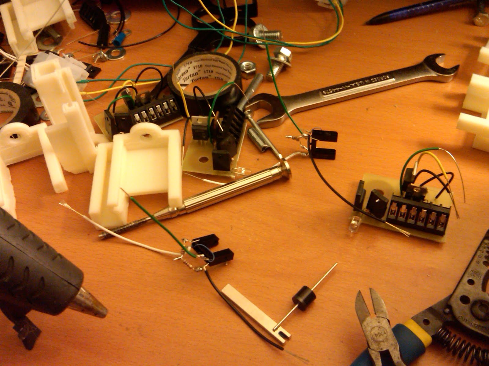
The real cost of 1-off engineering is the effort to design it. Most of the components are only about 4x the price they would be if bought in maximum bulk.

As a result, anything that can be designed once but fabricated and used many times is a big win. The rifle's many accelerating magnets is a perfect situation to exploit in this way. Each magnet will have it's own control circuit and it's own capacitor. I'll design a circuit once. I'll make 12 of them.

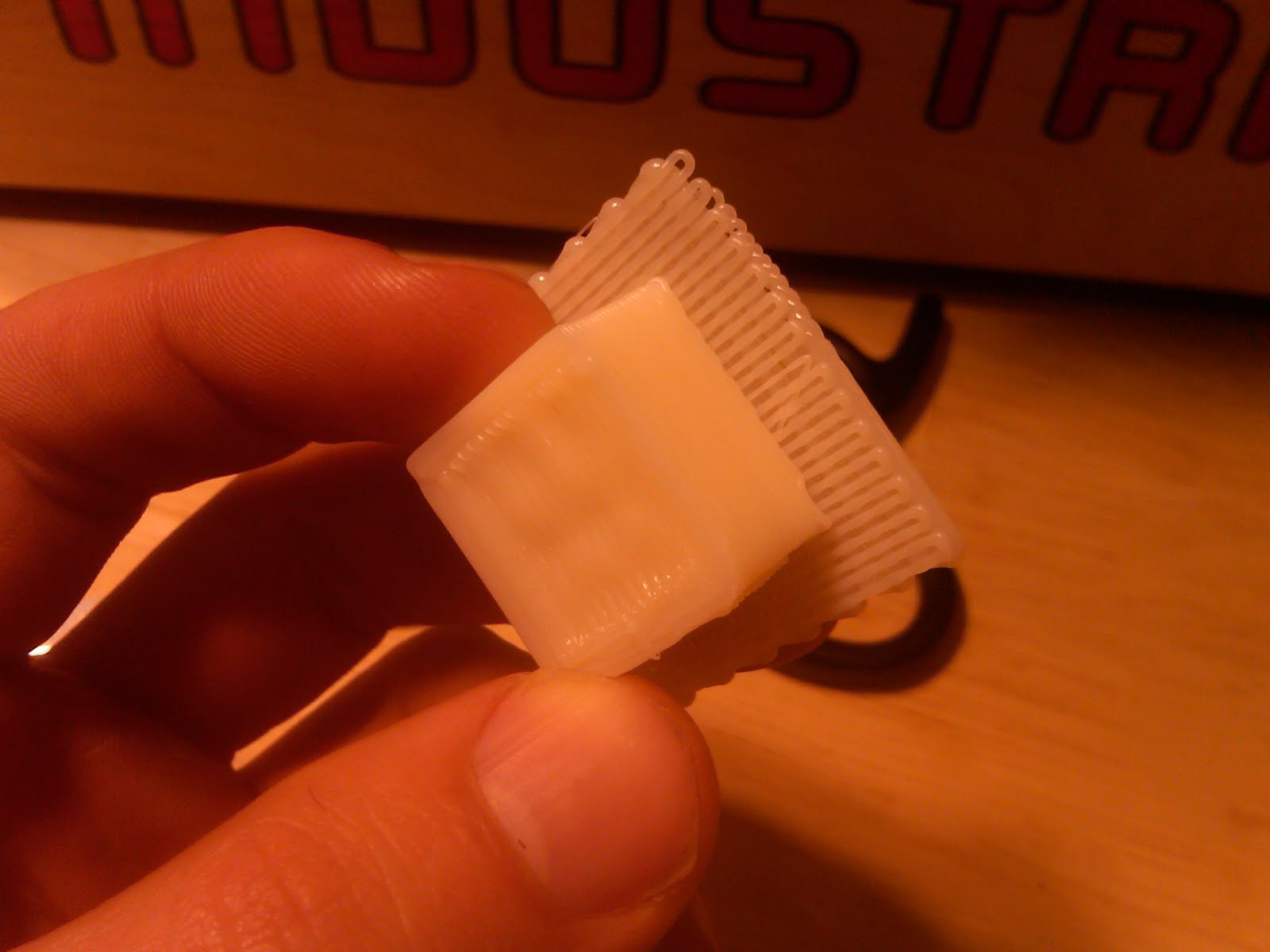
Everything mounts on a meter long, aluminium, square tube. I've spaced the accelerator magnets out with 6cm between them and I'll drill the bar accordingly. Each component will need to have it's own bracket to hold it in place and for this I'm intending to use a 3d-printer that's scheduled to arrive in a few weeks.

In the meantime, there's plenty of time to design the parts I'll be asking the machine to build. For this, I've used OpenSCAD. It's essentially a language for writing objects. This was my first time at writing actual objects.

In case you've never used such a product, it's essentially done adding or removing shapes. I started with the intention of making parts by a combination of subparts. So if there was a half cylinder that would hold the magnet and then a rectangular chunk that would hold it to the aluminium bar, I'd make each of the independantly and then join them. This turned out to have a lot of complexity in exactly how they were joined. It's very easy to end up with one part sticking out of the inside of the other in an unintended way.

Instead, I ended up making an object with a series of added shapes and a series of removed shapes with very minimual heiarchy.

As you can see from the code below, it was only about half way through that I also chose to start using variables instead of hard coding the sizes. (For whatever reason it cleared out my tabbing.)

//Coil

//85mm long

//29mm wide (14.5 rad)

//Cap

//50.5mm wide

//92.6mm long

//Bar

//19.4mm wide

//8mm hole

//10mm from hole center to bar top

//Circuits

//45mm Outer range

//35mm inner range (not w diode)

//20mm high (w diode sticking out)

//LittleBolt

//Nut: 9.35mm

//Bolt: 4.65mm

//Head: 8.98mm

//Thread lenth: 15mm

//BigBolt

//Bolt:12.58mm

//Threads: 30mm

coilRad = 15;

coilLength = 20;

coilWall = 5;

capRad = 26;

boltRad = 4.5;

lilBoltRad = 2.5;

circuitOuterRange = 45;

circuitInnerRange = 35;

circuitHeight = 20;

circuitBoardWidth = 3;

circuitWidth = 3;

circuitBaseWidth=14;

circuitBoltSpacing = 10;

module circuitHolder()

{

difference()

{

union() //added

{

cube(size=[circuitWidth*2+circuitBoardWidth,circuitOuterRange+2*circuitWidth,circuitHeight], center=true);

translate([0,0,-circuitHeight/2-1])

cube(size=[circuitBaseWidth,circuitOuterRange+2*circuitWidth,circuitWidth],center=true);

}

union() //removed

{

translate([0,0,1])

cube(size=[circuitWidth*4+circuitBoardWidth, circuitInnerRange, circuitHeight+2], center=true);

translate([0,0,1])

cube(size=[circuitBoardWidth, circuitOuterRange, circuitHeight+2], center=true);

translate([0,circuitBoltSpacing/2,0])

cylinder(h=circuitHeight+2*circuitWidth+2,r=lilBoltRad,center=true);

translate([0,-circuitBoltSpacing/2,0])

cylinder(h=circuitHeight+2*circuitWidth+2,r=lilBoltRad,center=true);

}

}

}

module coilCradleTop()

{

//add parts, then remove parts

difference()

{

union() //added parts

{

cylinder(h = coilLength, r=(coilRad+coilWall), center = true); //Outer cylinder

translate([coilRad+circuitBaseWidth/2+coilWall-1,0,0]) //Circuit holder

cube(size=[circuitBaseWidth+2,circuitWidth*2,coilLength], center=true);

translate([-coilRad-circuitBaseWidth/2-coilWall+1,0,0]) //Circuit holder

cube(size=[circuitBaseWidth+2,circuitWidth*2,coilLength], center=true);

}

union() //removed parts

{

cylinder(h = coilLength+2, r=coilRad, center = true); //inner cylinder

translate([0,36/2,0]) //Cube to remove top of cylinder

cube(size=[100,36,100], center=true);

translate([coilRad+circuitBaseWidth/2+coilWall-1,0,0])

{

translate([0,0,circuitBoltSpacing/2])

rotate([90,0,00])

cylinder(h=100,r=lilBoltRad,center=true);

translate([0,0,-circuitBoltSpacing/2])

rotate([90,0,0])

cylinder(h=100,r=lilBoltRad,center=true);

}

translate([-coilRad-circuitBaseWidth/2-coilWall+1,0,0])

{

translate([0,0,circuitBoltSpacing/2])

rotate([90,0,00])

cylinder(h=100,r=lilBoltRad,center=true);

translate([0,0,-circuitBoltSpacing/2])

rotate([90,0,0])

cylinder(h=100,r=lilBoltRad,center=true);

}

}

}

}

module coilCradle2()

{

//add parts, then remove parts

difference()

{

union() //added parts

{

translate([0,-70/2-10,0])

cube(size=[30,70,20],center=true); //Main block,

cylinder(h = coilLength, r1 = (coilRad+coilWall), r2 = 20, center = true); //Outer cylinder

translate([coilRad+circuitBaseWidth/2+coilWall-1,0,0]) //Circuit holder

cube(size=[circuitBaseWidth+2,circuitWidth*2,coilLength], center=true);

translate([-coilRad-circuitBaseWidth/2-coilWall+1,0,0]) //Circuit holder

cube(size=[circuitBaseWidth+2,circuitWidth*2,coilLength], center=true);

}

union() //removed parts

{

cylinder(h = coilLength+2, r=coilRad, center = true); //inner cylinder

translate([0,36/2,0]) //Cube to remove top of cylinder

cube(size=[100,36,100], center=true);

translate([0,-70,0])

cube(size=[20,20,100],center=true);

translate([0,-70,0]) //Lower bolt

rotate([0,90,0])

cylinder(h=80,r1=boltRad,r2=boltRad, center=true);

translate([0,-40,0]) //Upper bolt

rotate([0,90,0])

cylinder(h=80,r1=boltRad,r2=boltRad, center=true);

translate([0,-40,0]) //removed main section (for weight)

cube(size=[20,30,20],center=true);

translate([coilRad+circuitBaseWidth/2+coilWall-1,0,0])

{

translate([0,0,circuitBoltSpacing/2])

rotate([90,0,00])

cylinder(h=100,r=lilBoltRad,center=true);

translate([0,0,-circuitBoltSpacing/2])

rotate([90,0,0])

cylinder(h=100,r=lilBoltRad,center=true);

}

translate([-coilRad-circuitBaseWidth/2-coilWall+1,0,0])

{

translate([0,0,circuitBoltSpacing/2])

rotate([90,0,00])

cylinder(h=100,r=lilBoltRad,center=true);

translate([0,0,-circuitBoltSpacing/2])

rotate([90,0,0])

cylinder(h=100,r=lilBoltRad,center=true);

}

}

}

}

module capHolder()

{

difference()

{

union() //Added parts

{

cylinder(h=70, r1=(52+10)/2, r2=(52+10)/2,center=true); //Outer cup

translate([0,(52+10)/2+20/2-4,0]) //Main bolt holder

cube(size=[30,30,70],center=true);

}

union() //Removed parts

{

translate([0,0,5])

cylinder(h = 70, r1=52/2, r2 = 52/2, center=true); //Inner cup

translate([0,0,-15])

{

translate([0,(52+10)/2+20/2-2,0])

cube(size=[20,15,100],center=true);

translate([0,60,10])

rotate([90,0,0])

cylinder(h=40,r1=boltRad,r2=boltRad, center=true);

translate([0,60,40])

rotate([90,0,0])

cylinder(h=40,r1=boltRad,r2=boltRad, center=true);

translate([0,(52+10)/2+20/2+7,50])

cube(size=[boltRad*2,10,20],center=true);

translate([0,(52+10)/2+20/2+7,-30])

cube(size=[boltRad*2,10,80],center=true);

}

//Removed part for weight reasons

translate([0,0,15])

{

rotate([0,90,33])

cylinder(h=100,r=10,center=true);

rotate([0,90,-33])

cylinder(h=100,r=10,center=true);

rotate([0,90,90])

translate([0,0,-50])

cylinder(h=100,r=10,center=true);

}

//Removed part for weight reasons

translate([0,0,-15])

{

rotate([0,90,33])

cylinder(h=100,r=10,center=true);

rotate([0,90,-33])

cylinder(h=100,r=10,center=true);

rotate([0,90,90])

translate([0,0,-50])

cylinder(h=100,r=10,center=true);

}

}

}

}

translate([20+14/2,-25,0])

rotate([90,0,0])

circuitHolder();

translate([-70,70,0])

rotate([90,90,0])

capHolder();

translate([0,5,0])

rotate([180,0,0])

coilCradle2();

translate([0,-5,0])

coilCradleTop();