Friday, December 7, 2012

Two of something

As a mad engineer, it's a very special moment in my life when I get to make two of something. For starters, the second one is always better. But more importantly, making two means I didn't make a device, I made a design.

A single device helps you. A design helps the world. And to make a robotic controller with a set of robots, that's just fucking sweet.

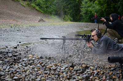
ShootingOnFourTargetsSCAR308

ShootingOnThreeTargetsWithAR15

Sunday, November 11, 2012

Girl shoots 24W laser gun vs. robotic targets running chaos mode algorithm

I shoot a 24W laser vs. robotic targets on chaos more algorithm

Me shooting the laser gun against robotic targets

Erin with 24W laser vs. robotic targets

Testing the active targets

As one might expect based on the level of testing we'd done, the active target worked but perfectly. This is a list of the errors we saw, roughly in order of importance:

  • Slipping motor connectors: The targets would exhibit an oscillation when the motor-to-target coupler started slipping. The solution for now is to use super-glue to attach them permanently. This does make removing and replacing parts difficult. I'm considering some tests with nut/bolt locking putties.
  • Hard to transport: The targets do stack next to each other but don't fit in a trunk without taking the side posts off. I don't want people to have to take the side posts off. I'd love if they could just snap into the bases. Then each could be transported separately.
  • Targets were shaken off:The abrupt movement of the targets caused them to share free. Like we any target affixed a piece of cardboard across the two wooden side supports. We then stapled paper targets to that. The cardboard was often shaken free of the side supports, ripping through the two 10mm staples we'd put on each side. No solution yet.
  • Controller was out of range: We had the controller box behind the targets and it only fired at some angles even though the targets were about 20 yards away. I'm considering replacing it with a foot switch. I may still need a relay and just have the foot switch activate the relay so we're not sending the full current to run all the way down the line to the switch and back. This will be especially true if it's ever used for long range shooting.
  • Algorithms were too short:Especially with the controller almost out of range, having only 3 or 4 rounds in a set felt like way too few. Longer rounds might also help train for reloading. We were able to reprogram the box in the field because I brought a computer.
  • Side posts are poorly attached: They're held on with duct-tape. This looks crappy but none of them fell off.
  • Ethernet jacks came loose: The plugs are only hot-glued on and one of them ended up loosely attached after being plugged and unplugged a few times

Active Targets Video 3

Active Targets Video 2

Active targets Video 1

Wednesday, October 24, 2012

Target Stand: IC is here

New printed boards to run the targets have arrived. For once in my life, I may not have made a significant mistake on these boards. I found exactly two sets of holes that were off and not by enough to matter.

I've done verification of the connections with the motor and the encoder on the target stand. I've also double checked the connections on the DC-motor-controller. Therefore, it's time to solder. And talk about what exactly I have here...

For starters, the goal of this device is to run 4 target stands from a single controller. It can then run an algorithm of targets to shoot on those 4 stands.

First things first: The connection with each target is an ethernet port. This was a tough call. I worked hard to reduce the number of connections needed but just couldn't. I need 2 to run the motor and 3 for the encoder, which tells me it's position. I could buy a special connector and use wire that's shielded (since some of the info is low-power analog). Or I could just use one of the most common connector ever: Ethernet. The wires have 8 connectors, can handle plenty of current for what I need (less than 200mA for the motors), and I'm pretty sure they're shielded. The only problem is that I'll risk some dumb shit plugging the target controller into an actual computer and frying it. Just this once, I'm going to trust humanity remember simple instructions like that.

Next up, the microcontroller itself: The arduino Uno is a very convenient device. I've used PIC chips which are cheaper but they often have special interfaces that most people won't have and therefore couldn't easily configure. Also, if you've ever used other less-user-friendly microcontrollers you'll find there's an endless mess of configuration you have to sort though. Sometimes it's easy and it just works. Sometimes you can't get entire sets of pins to work because they're configured for some other function and it's impossible to figure out how to turn that off. So I'm using a more friendly and user-modifiable microcontroller.

Now, how do we attach the arduino? Set a bunch of pins out of our board that are in exactly the same position as the plugs of the arduino. Then we can just plug our board into the arduino board.

Otherwise, I've got my simple DC motor controller in there and a rotary switch that'll be use to select and tell the microcontroller which algorithm to use.

This weekend, I expect to have a chance to actually run the targets and see what yet undiscovered errors I've made that prevent this from working. :)

Saturday, October 20, 2012

New PCB printer: ExpressPCB

If I need to prototype a circuit, I'll do it with wire wrap. I've found this is much more reliable than perf boards (where you just press the parts in at the right places). For some reason those always break on me and then I get inconsistent results from the circuits I build there. I think a major problem on my end is using components that are too big and then I have to really jam them in.

When the time comes that I need to make many of the same circuit (which is idea, design once and use again and again) then I need to get PCBs printed. I used to use pcbsingles.com in which you could draw the picture in paint or draw and they'd automatically print and drill it. Recently I placed an order and found they were out of business. When the owner told me this, I asked for a recommendation and he noted this place: ExpressPCB

ExpressPCB has their own board design software, but it's free and actually quite good. Much easier than doing this work in draw. And they're clearly encouraging you to do the circuit layout and then the routing. I haven't tried that yet since I knew many of my components wouldn't be in their library and I needed to have certain ports facing the outside, etc.

I just placed my first order and we'll see how it turns out. Hopefully I didn't fuck it up.

Tuesday, October 9, 2012

Target stand V2

I've made a new target stand. And a lot of errors... that I've since corrected.

The main error I've made is that I tried to violate one of the core rules of engineering: Don't build it if you can buy it. I tried to build a DC motor controller.

I was building a DC motor controller because this new target stand is powered by a DC motor. It has to turn both clockwise and counter clockwise. I already needed such a motor controller for my big moving table, so I figured I'd just finish making it.

So I built an H-Bridge. Initially it was able to show me +/- 5V when I asked it to. Perfect, works the first time! And it burnt out once I put it on a 12V power supply. Some internet searching and logic informed me that it turns out is suffered from something called 'shoot through'. This can be solved with the use of special H-bridge motor controllers.

I build a new motor controller on the perf board of the old one, and it didn't work at all. I build it on a proto-board and it didn't work. I tried two different kinds of H-bridge motor contollers and they didn't work. Maybe the old perf-board mosfets were more fried than I thought. Maybe the proto-board was broken from pushing parts that were too big into it. I don't have another day to waste on that. Fuck it.

Since this is a low power motor controller, I just bought one. I don't need a high power controller like the table will. They're like $6. What was I thinking?

Slap that shit together and now the table works, again powered by an arduino. At the end of the video you can see it fall apart, turns out I only put a single spot weld on the axle holder. The next day I painted that steel on thick and it works like a charm again.

Sunday, October 7, 2012

Target stand V1


This first target stand is clearly very basic. It's actually powered by a car door lock, which will pull the stand into position and then it's returned by a spring.

I went with a car door lock as the actuator because it is strong (10lb pull) and car door locks are common enough to be very cheap (~$15).

The problem is that in order to show the target, the actuator has to be pulling constantly. After about 1/2hr of turning the actuator on and off I noticed it was getting sluggish. On closer inspection that actuator is very hot. On measurement, the actuator was pulling 2 amps while it was on. This is not acceptable, far too much heat. After significant work, the machine is going to overheat. I need a different system.

Sunday, September 23, 2012

Target Stands

Question: What is an active target?

Answer: An active target moves on it's own. Re-active targets are already quite common in the world. The simplest version being a single plate of steel that, of course, makes a *ping* noise and moves when you shoot them. By contrast the active target will move into and out of sight to make shooting that target harder


Question: Why would you build one?

Answer: I'm guessing that if the targets at the range also move it will make me a more reactive shooter and be a better game to play. The problem is that the only active target I've seen for sale is LaRue's ~$1500 popup targets.

Question: How can you build it better?

Answer: The 'professional' versions here use a big steel plate that you shoot at. This means you can't use large weapons like a 50BMG. This also means you need a big engine to move it up and down quickly. And then you need a big steel plate to protect all the machinery that moves it up and down. And a big battery to power that motor. Etc. Etc.

Instead, I'm going to have a simple paper or wood target that isn't going to try and resist bullets. Similarly, instead of having the target lying down and pop-up, it'll be cheaper from a power perspective to have the target turn on an axis.

Saturday, August 11, 2012

Mech: Understanding strength and deflection of truss structures

Have you ever wondered whether a truss with a single cross bar is better than a truss with many of them? How many cross bars exactly do we need?

Sure, we see a lot of things with truss bars at 45-deg angles so we can assume smart engineers determined this was best. But was it best for reducing deflection or was it best for strength to weight? If they were doing it for total strength to weight but not for deflection to weight, I might want to do it differently.

Let's start with strength calculations of the single cross-brace truss. If we assume the weight of the steel in each beam is 1 lb/ft and the truss is 3' then we end up with 11.16lbs for the truss.

What's the strength of that truss? Let's assume the steel will not buckle or compress, and it has a pull strength of 10,000 lb/beam. So if a beam was hung vertically and we put 9,999lbs on it, it'd be fine. If we put 10,001lbs on it, it'd break. If we put a weight on the end of this truss we see that center beam will break at a weight of 3,160 pounds on the end.

What about if we had that same 3' truss with 3 spans? Now the weight is 14.24, a lot heavier. What's the strength? This is harder to calculate. The way to do it is one truss section at a time. Let's start with the last truss section, it will take 7,070 pounds to break that center beam. What about the one before it? Well the last truss section only adds a few pounds of weight so this one will also break at around 7,070 lbs. Same with the section before this. So this truss is actually the strength of any one section, assuming the weight of the truss is negligible.

If we divide the weight a truss can hold by it's own weight, the multi section truss gets a ratio of 496 while the single section truss gets only 283. So the multi section truss is 75% stronger for it's weight.

What about deflection? Does the single truss deflect less? Could that be an advantage?

I made a model of this on my nifty new structure simulating I've been using for the mech. I allowed for 20% stretch in the sections that would be experiencing it; both the top piece and the cross bar of each section. I modeled trusses with 1 section, 3 sections, and 6 sections. The 3-section truss puts each cross bar at exactly 45 degree angles.

It's easy to see from the model the 3 section truss is deflecting less. It deflects 1.8' while the 1 section truss deflects 2.2', 22% more. Then again, the 3 section truss weighs 28% more. Here though I don't think we can just take the weight ratio. The weight ratio was appropriate before because we could just thicken the truss bars to increase weight and strength linearly. The bar thickness will not have a linear relationship with deflection. For starters we haven't defined what the stretch algorithm is, we just set it to 20% arbitrarily.

How are we going to get a handle on this? For starters we know that stretch is usually linear with strain in steel. And that mild steel will top out around 0.2% stretch before it breaks. So if we made our bars in the 1 section truss 28% thicker, we'd reduce the stretch about 28%; to 0.1448% stretch. Now our two sections are of equal weight but the 1 section truss deflects 20% less.

Unfortunately, to get here I had to make an assumption about the stretch on the top of the truss, that we're going to have all truss sections of equal thickness, and that buckling never happens. But in the end it's clear the many-section truss is shit, the truss with 45-deg cross bracing is strongest by a good margin, and the 1 cross brace truss probably has the least deflection but only by about 20% of minimum possible deflection.

Sunday, July 15, 2012

Mech: More detail on the feet and legs

The real goal here is to get the models to fully represent the mech. Now the act of modeling everything in detail will force me to consider the entire design before I start building and serve to make the simulations work just like the final product will.

Sunday, July 8, 2012

Mech: Material Science

I had some problems with the mech's feet and their colossal weight. I've made some reductions in the main spans to get the margin of error to about 8X it's standing strength. I also made the assumption I'd be using an alloy steel that's about 2x as strong (125k psi instead of 60k psi).

This has brought the mech feet down to 298lbs each, which is exactly under my target weight.

I'll need to do more calculations about the torsional forces on the foot that I've not yet figured out how to do. I also bought a book on material science to better understand what I'm doing now that I'm relying on more complex material properties for strength.

Also, while I was mulling over my changes to the mech I spent some time working on the table. I finished the H-bridge controlled that will drive the motors. It needed some debugging but then when it 'worked' it blew up, fracturing one of the transistors with the heat. It's clear there was a moment when both the high and low on one side were both conducting, allowing a high amperage of 120V through it.

Investigating some non-home-made H-bridge drivers I see that they often tout their abilities to prevent this. I bought some. I hope that their bragging about this feature does not imply that some of them still fail at it...

In other news, I left the soldering iron on when I got distracted by an attractive girl in my bed and need to buy a new tip for it.

Sunday, July 1, 2012

Mech feet: It looks like they're too heavy

I just added the density settings to the mech feed that I designed and it looks like they're already super heavy. Just one foot is 852lbs.

I'm using 3"x3"x0.25" steel for the main spans, 2"x2"x0.25" for the long (1") cross bracing, and 1"x1"0.25" for the short cross bracing.

Mech feet

The goal at this point is making the mech match what I'll actually build. That way the simulations will be accurate enough to determine the exact walking sequence. Similarly, I'll be able to get the collision detection and weight measurements correct.

Got the basic supports done for the mech foot. I'm using a helix or spring-like pattern to prevent the truss that connects to the leg from bending in the face of the torque from the feet. I'm not yet sure how to measure the stresses on it.

Saturday, June 30, 2012

Mech: Structural calculations

The next stage of mech design is actually designing the steel structure of it's feet and legs. This will also be my first trip into the land of structural engineering.

So how beefy do those feed need to be? Let's assume for now that we've got the center of mass at the center of the mech, 4' from the leg. And let's assume the feet extend 6' into the center. Given a 2000 lb mech, we now have 8000 ftlbs of torque and 1333 lbs of force felt on those foot spikes that extend toward the center and keep the mech from falling to one side of the other when it lifts a foot. Let's call that part the 'toe'.

If we assume there are two main bars in that support the toe and the foot is 1' high, the angle made by the bars is 9.5degrees. That works out to some 8110lbs of compression force felt by that top bar. The bottom bar will feel a tension force of about the same. Now the question is: what kind of bar do we need to handle that?

According to me metal supplier, onlinemetals.com, is takes ~60,200 psi to distort 316 grade stainless steel. (I'll probably not be able to make this thing entirely in stainless, but I like to dream) If I use a 1" diameter rod of stainless steel, it can hold 47,280 lbs. So that's more than enough.

That doesn't like it would be enough to hold 1 ton of mech at a bad angle does it? I suspect that my mind has a biased view of the strength of steel because I so often interact with tube steel rather than solid rods of it. Hold a solid 1" diameter rod and it's almost surprising that anything could break it.

So Now what about the ankle joint? There's a single rod that has to hold the foot to the leg. That rod must take the entire torque of holding the mech up. What kind of rod do I need there to keep it from sheering off with the force?

If we assume the leg supports are 6" apart (and remember, we now have 4 bones for each leg section), and apply the 8000 ftlbs of torque to it we come up with 16,000 lbs of sheering force on the bolt.

According to wikipedia, steel's sheer force is about 0.75 of the yield force. That comes out to 45,150 psi. If we use a 2" bolt here, it comes out to 3.1415 cubic inches of area and 141,842 lbs of sheer strength.

By the numbers we could use a 1" bolt with a sheer strength of 35,460 lbs but that's dangerously close to our 16,000 lbs limit. If we saw shock from ground impact or slipping, has temperature effects, or generally just mis-calculated that bolt could sheer and the mech would fall over. In reality, I'm probably going to use a 2" bolt for the ankle and maybe 3"x0.25" angle iron for the feet.

Of course, as always, I have no idea what I'm doing here. Thank science for textbooks and the internet...

Monday, June 25, 2012

50BMG: How good are they really?

I hear a lot about just how strong a 50BMG is. I wanted to know just how true all that was. So we pitted a 50 BMG, a 7.65x53 mauser, and a 5.56x45 AR-15 against a steel plate.

At ~700 grain the 50GMB is heavier than the 63 grain 5.56 and 174 grain 7.65. The 50BMG is firing out of a 29" barrel for a solid 2,500 ft/s vs the 2,460 ft/s of the mauser. Here the 5.56 scores better even out of it's 16" barrel at ~2,900 ft/s. That puts the 50BMG at ~10x the power of the AR and about 6x the power of the mauser.

For this test, we only have solid lead shot for the mauser but we've got basic (non-explosive) armor-piercing ammo for the 5.56 and 50BMG.

... and we have a 1" (~25mm) thick mild steel plate. Getting a hardened steel plate at this size would cost ~$300 and so we'll test hardened vs. mild steel with some smaller rounds and cheaper plates. I actually suspect hardening protects only slightly better or not at all better but does have the property of being all-or-nothing. That is a hardened target will be either totally broken through or shrug off the round entirely, while a mild target will get ever larger craters until it's broken through. But I digress, and we will have to test that.

At 100 yards, the 7.65 with solid lead makes only a 3mm crater in the steel. The 5.56 with armor piercing steel cores makes a 4mm crater. The 50BMG with armor piercing steel core is so close to passing through we can see the hardened steel center of it pushing ~1.5cm through the back of the steel plate.

It makes a big difference. But if anyone ever says a 50BMG can shoot through a tank, remind them that the purpose of tanks is to have rifles not be able to shoot through them. Modern tanks sport more than 100mm of composite armor.

Photos courtesy of our excellent friend who goes by the name 'Chris' until he comes up with a better internet alias.

Friday, June 15, 2012

Mech Speed

In considering the height, I decided to reduce the length of the legs segments to 4' each instead of 5'. That will put the maximum height of the leg sections at 8'. Along with a 5' cockpit/hip assembly and a 1' foot and ankle assembly this keeps the total walking height at under 14'. Which is the requirement of the US government to drive on the roads. I still have to work out how I'll get the feet to be so short, but I'll deal with that later.

It's also clear the changes have increased the efficiency of the legs. New efficiency is 8.0255. Stride of 6.33' with a actuator displacement of 0.79'.

What does that efficiency mean to us? We want to calculate the mech speed based on the stats we now know.

Lets start with the size of the actuators we're going to need. Assume the mech weights about 2,000lbs. At worst the leg will be at a 90 deg angle and the entire weight of the mech will be at a 4x leverage so each actuator will need to handle 8,000lbs. An actuator with a 3" diameter running at 1500psi will generate 10,602lbs of force so that will do.

At 3" diameter with a 0.79' total stroke per step we get 0.29gallons displaced per step. If we have an engine generating 5gal/s (~250lbs) this will make a step time of 3.48 seconds and a speed of 1.24 MPH. With a 10gal/s (~500lbs) engine this will be a step ever 1.74 seconds and a walking speed of 2.48MPH.

Of course, I also intend to have a 10gal accumulator. It will reduce in pressure as it drains so lets say I only get 5gal out of it at >1500psi. This works out to about 17 steps or about 109' before I'll be pulling from the engine again. There's no way to know exactly how fast a sprint will be at this point because that depends on just how quickly the actuators can fill and move. It may also depend on controlling the momentum of the device as we don't want the mech falling over when it stops.

Tuesday, June 12, 2012

Mech: Latest design

The mech simulations take a while. I have some larger, longer ones going but this is an initial one. I'm working on cleaning up the documentation and making sure all the tests work just fine so that I can had it to the wider world cleanly.

The stats of this simulation:

  • Stride length: 5.39'
  • Actuator displacement over the course of the movement: 1.05'
  • Efficiency: 5.13
  • Max height: 9.05'
  • Min height: 10.00'

How the simulation is choreographed:

The act of walking goes by a series of hard coded steps. I'm just asking the simulation to search out and find parameters for it.

Init: right foot forward, weight centered between feet (rtinit, rcinit, ltinit, lcinit)

  1. Left calf up and forward. (lc1)
  2. Right thigh pushes the whole machine to fully upright. (do a search for this value)
  3. Right calf also pushes to fully upright. The right leg is pushing up to let the left leg forward. (do a search for this value)
  4. Left thigh draws under the weight of gravity.
  5. Left thigh pushed the rest of the way forward. (rtinit)
  6. Left calf is released and set to draw under the presence of gravity. We at letting the leg down to keep the center of gravity from going too far forward. (do a search for this value)
  7. Left calf down. We don't have to check the ground distance here because we know this will work. (rcinit)
  8. Right calf to landing position. (lcinit)
  9. Right thigh continues to ltinit, making contact with the ground.

The left leg is now able to take the weight

The parameters of this mech walk:

  • Right Thigh Init: 1.744
  • Right Calf Init: 1.550
  • Left Thigh Init: 0.942
  • Left Calf Init: 1.550
  • Left Calf Step1: 1.744
  • Right Thigh Step2: 1.433
  • Right Calf Step3: 1.433
  • Left Thigh Step4: 1.433
  • Left Calf Step6: 1.433

Wednesday, June 6, 2012

Mech: Beginning work on 3D motion

I've gotten the basics of a system to empirically build efficient walking. Right now it's only criteria are that it cannot pass through the ground and that it must be at least 7' tall at it's lowest height.

This particular simulation still has a foot collision that you can see any it takes a stride that's dangerously long. I've spent quite a while working on a zero-approximations collision detection system that I'll be turning on next.

Friday, May 18, 2012

Mech: Legs designed in 3D

I had to work a few more bugs out of the location computing and rendering systems. I think the image is still flipped but I'll deal with that later.

For now, I have the legs and hip sections modeled. Not just their current location, but even their kinematics are modeled in this rendering system: If I adjust the actuators the entire structure will move and react. And all in about 70 lines of code, including constants and comments.

#Leg attributes

actThighInit = 1.0

actCalfInit = 1.0

actHipDis = 1.0

actThighDis = 1.0

actKneeDis = 1.0

actCalfDis = 1.0

thighLen = 5.0

calfLen = 5.0

legBoneDis = 2.0

hipWidth = 8.0

#DISPLAY PROPS

leftLegDispProp = displayProperties([100,100,255],2)

rightLegDispProp = leftLegDispProp

actDispProp = displayProperties([255,255,100],4)

hipDispProp = displayProperties([255,100,100],2)

leftHipBack = location(0,0,0)

leftHipActuator = location(actHipDis,0,0)

self.struct = structureSeed(leftHipBack,leftHipActuator)

s = self.struct

#LEFT LEG

leftThighActuator = s.addJoint(leftHipBack,actThighDis,leftHipActuator,actThighInit,location(0,1,0),'f',dispPropA=leftLegDispProp,dispPropB=actDispProp)

leftKneeBack = s.addJoint(leftHipBack,thighLen,leftThighActuator,dispPropA=leftLegDispProp)

leftHipFront = s.addJoint(leftHipActuator,legBoneDis+actHipDis,leftHipBack,dispPropA=leftLegDispProp)

leftKneeFront = s.addJoint(leftHipFront,thighLen,leftKneeBack,legBoneDis,leftHipBack,'f',dispProp=leftLegDispProp)

leftKneeBrace = s.addJoint(leftKneeBack,math.sqrt(1.0+legBoneDis*legBoneDis),leftKneeFront,1.0,leftHipBack,'n',dispProp=leftLegDispProp)

leftKneeActuator = s.addJoint(leftKneeBrace,math.sqrt(1.0+actKneeDis*actKneeDis),leftKneeFront,actKneeDis,leftKneeBack,'f',dispProp=leftLegDispProp)

leftCalfActuator = s.addJoint(leftKneeActuator,actCalfInit,leftKneeFront,actCalfDis,leftKneeBrace,'f',dispPropA=actDispProp,dispPropB=leftLegDispProp)

leftAnkleFront = s.addJoint(leftKneeFront,calfLen,leftCalfActuator,dispProp=leftLegDispProp)

leftAnkleBack = s.addJoint(leftAnkleFront,legBoneDis,leftKneeBack,calfLen,leftKneeActuator,'f',dispProp=leftLegDispProp)

#HIP

legHipSupportLen = 1.0

legHipWingLen = 0.5

hipPostLowerPoint = 0.1

hipPostUpperPoint = 1.0

hipCockpitDis = 1.0

cockpitWidth = 6.0

actHipInit = sqrt(sq(hipCockpitDis)+sq(actHipDis))

# Main leg supports

leftHipSupportBack = s.addJoint(leftHipBack,legHipSupportLen,leftHipActuator, sqrt( sq(legHipSupportLen) + sq(actHipDis)),leftThighActuator, sqrt(sq(actThighDis)+sq(legHipSupportLen)),dispProp=leftLegDispProp)

leftSupportAttachFront = s.addJoint(leftHipFront,actThighDis,leftKneeFront,dispProp=leftLegDispProp)

leftHipSupportFront = s.addJoint(leftHipFront,legHipSupportLen,leftHipBack, sqrt(sq(legBoneDis)+sq(legHipSupportLen)),leftSupportAttachFront, sqrt(sq(actThighDis)+sq(legHipSupportLen)),dispProp=leftLegDispProp)

# Hip post

leftHipWingBack = s.addJoint(leftThighActuator,sqrt(sq(actThighDis)+sq(legHipWingLen)),leftHipBack,legHipWingLen,leftHipFront,sqrt(sq(legBoneDis)+sq(legHipWingLen)),dispProp=leftLegDispProp)

leftHipPostUpper = s.addJoint(leftHipBack,hipPostUpperPoint,leftHipFront,sqrt(sq(legBoneDis)+sq(hipPostUpperPoint)),leftHipWingBack,sqrt(sq(legHipWingLen)+sq(hipPostUpperPoint)),dispProp=leftLegDispProp)

leftHipActuatorPost = s.addJoint(leftHipBack,sqrt(sq(hipPostUpperPoint)+sq(actHipDis)),leftHipActuator,hipPostUpperPoint,leftHipPostUpper,actHipDis,dispProp=leftLegDispProp)

# Hip center

leftHipCockpitUpper = s.addJoint(leftHipPostUpper,hipCockpitDis,leftHipActuatorPost,actHipInit,leftHipBack,sqrt(sq(hipCockpitDis)+sq(hipPostUpperPoint)),dispPropA=actDispProp,dispPropB=hipDispProp,dispPropC=hipDispProp)

leftHipCockpitLower = s.addJoint(leftHipCockpitUpper,hipPostUpperPoint,leftHipBack,hipCockpitDis,leftHipPostUpper,sqrt(sq(hipCockpitDis)+sq(hipPostUpperPoint)),dispProp=hipDispProp)

rightHipCockpitUpper = s.addJoint(leftHipPostUpper,cockpitWidth+hipCockpitDis,leftHipCockpitUpper,dispProp=hipDispProp)

rightHipCockpitLower = s.addJoint(leftHipBack,cockpitWidth+hipCockpitDis, leftHipCockpitLower,dispProp=hipDispProp)

rightHipPostUpper = s.addJoint(rightHipCockpitUpper,hipCockpitDis,rightHipCockpitLower,sqrt(sq(hipCockpitDis)+sq(hipPostUpperPoint)),leftHipCockpitLower,'f',dispProp=hipDispProp)

rightHipBack = s.addJoint(rightHipCockpitLower,hipCockpitDis,rightHipCockpitUpper,sqrt(sq(hipCockpitDis)+sq(hipPostUpperPoint)),leftHipCockpitUpper,'f',dispProp=hipDispProp)

# Hip post

rightHipActuatorPost = s.addJoint(rightHipBack,sqrt(sq(actHipDis)+sq(hipPostUpperPoint)),rightHipPostUpper,actHipDis,rightHipCockpitUpper,actHipInit,dispPropA=rightLegDispProp,dispPropB=rightLegDispProp,dispPropC=actDispProp)

rightHipActuator = s.addJoint(rightHipActuatorPost,hipPostUpperPoint,rightHipBack,actHipDis,rightHipPostUpper,sqrt(sq(hipPostUpperPoint)+sq(actHipDis)),dispProp=rightLegDispProp)

#RIGHT LEG

rightHipWingBack = s.addJoint(rightHipPostUpper,sqrt(sq(hipPostUpperPoint)+sq(legHipWingLen)),rightHipActuator,sqrt(sq(legHipWingLen)+sq(actHipDis)),rightHipBack,legHipWingLen,dispProp=rightLegDispProp)

rightThighActuator = s.addJoint(rightHipActuator,actThighInit,rightHipBack,actThighDis,rightHipWingBack,sqrt(sq(legHipWingLen)+sq(actThighDis)),dispPropB=rightLegDispProp,dispPropA=actDispProp,dispPropC=rightLegDispProp)

rightKneeBack = s.addJoint(rightHipBack,thighLen,rightThighActuator,dispPropA=rightLegDispProp)

rightHipFront = s.addJoint(rightHipActuator,legBoneDis+actHipDis,rightHipBack,dispPropA=rightLegDispProp)

rightKneeFront = s.addJoint(rightHipFront,thighLen,rightKneeBack,legBoneDis,rightHipBack,'f',dispProp=rightLegDispProp)

rightKneeBrace = s.addJoint(rightKneeBack,math.sqrt(1.0+legBoneDis*legBoneDis),rightKneeFront,1.0,rightHipBack,'n',dispProp=rightLegDispProp)

rightKneeActuator = s.addJoint(rightKneeBrace,math.sqrt(1.0+actKneeDis*actKneeDis),rightKneeFront,actKneeDis,rightKneeBack,'f',dispProp=rightLegDispProp)

rightCalfActuator = s.addJoint(rightKneeActuator,actCalfInit,rightKneeFront,actCalfDis,rightKneeBrace,'f',dispPropA=actDispProp,dispPropB=rightLegDispProp)

rightAnkleFront = s.addJoint(rightKneeFront,calfLen,rightCalfActuator,dispProp=rightLegDispProp)

rightAnkleBack = s.addJoint(rightAnkleFront,legBoneDis,rightKneeBack,calfLen,rightKneeActuator,'f',dispProp=rightLegDispProp)

rightSupportAttachFront = s.addJoint(rightHipFront,actThighDis,rightKneeFront,dispProp=rightLegDispProp)

rightHipSupportFront = s.addJoint(rightHipBack,sqrt(sq(legBoneDis)+sq(legHipSupportLen)),rightHipFront,legHipSupportLen,rightSupportAttachFront,sqrt(sq(actThighDis)+sq(legHipSupportLen)),dispProp=rightLegDispProp)

rightHipSupportBack = s.addJoint(rightHipActuator,sqrt(sq(actHipDis)+sq(legHipSupportLen)),rightHipBack,legHipSupportLen,rightThighActuator,sqrt(sq(actThighDis)+sq(legHipSupportLen)),dispProp=rightLegDispProp)

Friday, May 11, 2012

Mech: The 3D rendering and image export works

I've got the new 3-d rendering system online, rendering, and exporting images. The image shown here was built using the code below

The first three lines of this code are the basic bootstrapping. We put two locations in space. We build out structure seed from that. I then define a display property to be able to highlight one of the spans. Then, the first two 'add joint' commands are using the 2D building ability. When building an object from only two points, I have to make up a third one in order to define what plane the new point should be in. I also need to say 'far' or 'near' relative to the made-up point that defines the plane since there are usually two possible solution points. The last 'add joint' is a regular 3D joint, made from three of the other joints.

You might notice that we constructed this pyramid without all of the pieces. In designing machines, this will actually be a valuable feature since it prevents you from making machines that *can* bind. This way, you must make models that are minimally determined and thus maximally able to move when their joints move.

nearL = location(0,0,0)

nearR = location(1,0,0)

s = structureSeed(nearL,nearR)

highlightDisProp = displayProperties([100,100,255],7)

farL = s.addJoint(nearL,1,nearR,math.sqrt(2),location(0,0,1),'f')

farR = s.addJoint(nearL,math.sqrt(2),nearR,1,location(0,0,1),'f')

top = s.addJoint(nearL,1,nearR,1,farL,1,dispPropA=highlightDisProp)

Lastly, I've uploaded the code for this. It requires both pygame and imagemagick (just to apt-get installs on them). Run the command 'python main.py' to make it do it's thing.

https://docs.google.com/open?id=0B1S9HNoTaV32Y20wRjVhNzBfd0U

Monday, May 7, 2012

Mech: Building the 3D simulator

I needed a 3D simulator. There are lots of programs that let you draw objects and place them. I didn't see offhand any that have the simulator compute the locations of things based on their distances from other things. And it would have taken me a while to find the right one with the right APIs so I just didn't.

Instead I'm making a 3D simulator. Like the 2D version I already made it computes locations based on relative distances from other locations. I've added compatibility with 2D as well as lines for convenience.

Today, I got it computing locations even for the complex 3D cases. The interesting part of this was doing a bunch of rotations until the points were in a plane where I could compute the solutions to them.

I solve the problem in two major parts. Each part is essentially solving for the intersection of two points. So let's say I have joints A,B,C and distance dA,dB,dC from the new joint D that we're going to place. I start with joint A and joint B. I solve for where D is relative to them. But in a 3D world that's actually a circle. Based on the location of C and dC I can find a specific point on the circle D. Below are the exact steps:

  • STEP 0: Copy initial points so they never drift with repeated transformations
  • STEP 1: Translate to make point 1 the origin
  • STEP 2: Rotate around Y axis till point 2 lies in Z=0 plane
  • STEP 3: Rotate around Z axis till point 2 lies in Y=0 plane (now must be on the X-axis)
  • STEP 4: Solve for point 4(new point)'s to find the X and Y. The X here will end up being the real X in this space. The Y is simply the radius.
  • STEP 5: The problem now starts over, remaking a new point A and B based on the X,Y we solved and point 3
  • STEP 6: Translate to make point newA's X=0
  • STEP 7: Rotate around Y axis 90 degrees to make the solution circle lie at Z=0
  • STEP 8: Rotate around Z axis till point newB lies on the Y=0 plane (it now must be on the X-axis)
  • STEP 9: Solve for point 4(new point)'s to find the new X and Y locations. The transformations we've already done will fill out all the other data found along the way.
  • STEP 10: Build the solution
  • STEP 11: Back out all transformations

If you spend a few minutes thinking about this, you'll notice that the points and distances is not enough to determine an exact point. It determines one of two points. As with the 2D system, I'm solving this by using the right hand rule. If you list the points clockwise from your perspective, whatever perspective you choose, the plane those points in will be between you and the new point. Take a sec to think about it.

To give an example test case I run:

#Test case: 3D joint

j = joint()

j.jointA = location(1.0,0,0)

j.jointB = location(0.0,1.0,0.0)

j.jointC = location(0.0,0.0,1.0)

j.spanA = span(1.0)

j.spanB = span(math.sqrt(1+1+1))

j.spanC = span(1.0)

j.computeLocation()

if(j.x > 1.01 or j.x < 0.99 or j.y > 0.01 or j.y < -0.01 or j.z > 1.01 or j.z < 0.99):

\t p = False

\t print "ERROR on test case 8: %s"%j.toString()

I've decided to call the new rendering and computing engine MindFuck3D. From this post, I hope you can begin to see why. Once I try to actually design in this new language I think it will really win it's name. It will be difficult to get good at but very quick and powerful once I have it down.

Wednesday, April 25, 2012

Mech: Visualizing a simple walk sequence

I've added color and sequencing to the simulator. I've also added a cockpit (red) and an engine (grey) to the mech to show better what it will look like.

The simulator is good enough to be able to simulate many possible walk sequences. I wrote a function that tries many many actuator combinations to come up with a walk sequence that fits a few basic criteria:

  • Starts with both feet on the ground
  • Does not drop the cockpit height below 8'
  • Maximize stride (I've not yet modified it to maximize efficiency)

I then fed the computer-chosen result through a function to show the sequence and spit out some diagnostics about the walking movement:

  • Stride length: 6.7'
  • Actuator displacement through a single step: 1.4'
  • Efficiency (stride/displacement): 4.79

I noticed in the course of doing this that the certain actuator positions increased efficiency. However, I suspect they also rely on greater actuator strength. Right now I'm counting all actuator displacement to be made equal. In reality, the difficult of moving the actuator isn't just in the distance it travels but also the force on it. To compute this function automatically I'll have to add a ton of statics equations to the simulator.

Notice that in addition to the simple walking sequence I've added the crouch distance. For this configuration it stands with a hip height of 8.7' and a minimum crouch distance of 4'.

Wednesday, April 18, 2012

More mech simulator

Added some more functionality to the simulator. In particular colors. We can see now the two legs and the actuators that control them. We can also execute commands to lengthen or reduce the length of those actuators. I'll be adding stats and auto-calculation of the structure next. This one will be particularly interesting. I've not yet decided if I'm going to calculate it or have the machine find it by trial and error. After that probably a third dimension.

Monday, April 16, 2012

The beginnings of the mech simulator


I decided I needed some computer aided design, beyond the excel spreadsheet I was using. I need a mech simulator. The mech simulator has several goals:

  • V1: Show the mech based on the dimensions and actuator positions

  • V2: Indicate bob-height when walking

  • V2: Indicate stride when walking

  • V2: Indicate max/min height

  • V2: Indicate foot colissions when running walking sequence

  • V3: Export information to open-scad for 3-d rendering and model printing

  • VNext: Load calculations

  • VNext: Inertia calculations


After a bit of playing around I found the best way was just to specify new joints and place them at distances from previous joints. I wanted to make something easier/cheaper and more specific to this project but there was no value in not making it general. This joint-adding approach makes it easy to write out the dimensions of whatever you're making. It works for single-leg-bone designs. It works for parallel-leg-bone designs like what I will probably use.

I still have to work out the dimensions myself, but once I have a sequence of commands and information about walking I'll be able to play with that much more dynamically.

Eventually the V2-VNext features will allow me to expand and finalize my designs while still being able to react to fuck-ups I make.

Wednesday, April 11, 2012

So I've decided to build a mech and I want your help


There's a lot of work to do.
1. Statics analysis on how a two-bone leg is different from a one bone leg. I can eliminate an actuator by doing design A and don't think it changes the force equations much but I don't know. At some point I'll do the statics equations but anyone can do that right now. (see diagram)
2. Research availability and prices on hydraulic cylinders/actuators that have built-in encoders. As in a measure of how far the cylinder has extended. All the exterior encoders I've seen will mountings, calibration, etc. It must be something with a price, at least a quote if not an add-to-cart style for purchasing. There's a lot of industrial parts makers that do not actually handle distribution and we need a distributor.
3. Other large-scale walking robots. Especially bipedal. I haven't seen any that actually walk. If there's not a video of it moving it's a BS project. Best I've seen is a 6-legged logging robot that's build not to damage foliage as it moves through the forest.

Pick one. Tell me what you find out.

Wednesday, March 28, 2012

Because they won't sell me a nuclear reactor

Let's say I wanted to build a mech warrior. A big walking robot.

I want to drive it on the road. A quick check of the laws says a max of 8.5' wide and 14' tall before you're a 'oversize load'. 14' tall is reasonable. Let's say 10 for legs, 4 for cockpit (you'll be sitting, maybe stretch those legs out).

What about power? They won't sell civilians nukes and I probably can't afford one anyways. So it'll have to be gas or diesel. But what about the actuators? This is too big for electric servos. Can't do pneumatics because they don't offer much in the way of position control: the gas will exert a certain pressure at a certain volume so generally pneumatics have to be railed out in one direction or another else their position will be unstable. Might also consider just a bunch of mechanics that move the legs at just the right times. But then it'll never be able to do dynamic things like crouch or lean forward. So it'll have to by hydraulics. They can hold position well. They're super strong. They're not terribly expensive.

If you're not familiar with hydraulics, don't worry, I'm not either. From what I read, there's no like 'reservoir of pressure' since hydraulic fluid is inelastic. So you have to pump up the actuators using an engine in real time. Here is such an engine: http://www.fostermfgcorp.com/page/gas/20_24_hp.html

Gas powered. 25 HP. 15 gal/min pumping speed @ 2000psi. That pumping speed is going to be a set rate probably even when the psi it needs to push is lower because it's probably just an engine turning some little pump at a set RPM. The pump moves a certain volume at that RPM and is rated to a max pressure of 2000. Notice how they come at different max pressures and volume rates. If they could dynamically run move volume at a lower pressure they wouldn't be priced like that.

How much can that engine power? Let's do some calculations about the mech. The engine is 450 lbs right off the bat. Two passengers is 350 lbs assuming a dude and a chick. Cockpit structure and fuel is say 200 lbs. If we say each leg is two 7' spans of I-beam at a 1/2" thick, 2" edge-wide, 3" center-wide then we have 588 cubic inches of steel in each leg. At 0.226 lbs/cu-in that's 133 lbs/leg. The feet will probably have to be at least that beefy since the force angles on them will be terrible and they'll have to be big for stability. Let's round leg weight up to 500 for actuators and feet. Total weight: 2000lbs.

How much force is on one of those legs? Let's assume the two spans that make up a leg are inverted, like chickens have. The knee is pointing backward and the acute angle of the knee faces forward. Near the hip, the leg is connected on a joint. Then there's a hydraulic actuator that connects a point farther down the leg to the hip. When that actuator expands, it pushes the thigh section to be more vertical and less horizontal. But where is the actuator exactly positioned?

Let's say the knee is at a 90 degree angle when standing. So the leg is at 45 degrees to horizontal. And let's put the actuator straight up and down while standing.

If we look up cylinders on McMasterCarr we see that a pretty common stoke length is 1' on a cylinder that's 1.5' long compressed. http://www.mcmaster.com/#62205kac/=gv8y5j

In the standing position we'll need the cylinder to be at least somewhat uncompressed because it will need to compress more if we ever want to take a step backward. So let's put it at 1.8' extension while standing. If it uncompresses out to 2.5' (it's max extension) and we put it, say 1.5' from the hip joint, the actuator will be able to move the thigh from an angle of 45 deg while standing to 68 deg (the math takes up some room so you'll just have to do it yourself or trust me). That's some, not a lot of angle. It'd be nice if the leg could at least get to vertical (90 degrees). But whatever, this is a first order approximation.

Again, how much weight is on this actuator? While standing the thigh is at a 45 deg angle, it's 7' long and the connection point is 1.5' away from the joint. So we have 2000lbs but it's being leveraged at 7*cos(45)/1.5 = 3.3x. The actuator feels 6,600 lbs.

Sure, we could move the actuator farther from the hip joint to reduce that multiplier but then our max extension angle would be even smaller.

What kind of actuator do we need for 6,600 lbs? Actuator strength is all about bore size and pressure. Power = pi * r^2 * pressure. Our engine runs up to 2000 psi. That returns a bore size of almost exactly 1". Let's use the 1.5" bore for safety. It will give us a 2.25x safety margin before the engine explodes or the mech collapses under it's own weight.

How quickly can our engine move that actuator? At a 1' stroke with a 1.5" bore we're going to consume 85 cubic inches of hydraulic fluid. Remember our engine can do 15 gal/min or 15*231 = 3,465 cubic inches per minute. 58 cubic inches per second. It can fully extend that actuator in 1.47 seconds. But if we assume there are 3 actuators per leg (hip-thigh, thigh-calf, calf-foot) and we're extending each of them only half way we're able to put one leg forward in 2.2 seconds. If an actual step is leg-forward, weight forward, leg-return we'll be taking a step every 7 seconds or so.

That's a slow step. It better be a big one.

How can we speed that up? Well, a nuke with a bigger hydraulic pump wouldn't hurt.

Wednesday, March 21, 2012

Chris was right


I should be using an H bridge. For some reason I had it stuck in my mind that supplying the gate voltage to the high-end transistors was going to be a bitch. It won't be a bitch. I just need to man up.

Sunday, March 18, 2012

Circuits: They make your abstraction barriers into their bitches

The goal: Making a DC motor controller that can reverse directions. This will be used on the grabber arm for the table mentioned in previous posts.

The initial concept: Make a DC rectifier that goes one way, turn it on when you want to go that way. Let's try it:


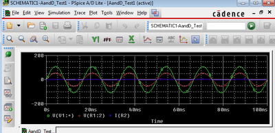
So let's talk through this circuit. Far on the left we see the power source, I found it in the 'SOURCE' library in Orcad PSpice. It has a 60Hz wave with 60V amplitude. I chose 60V because going higher seemed to short out the other parts in the simulation. In real life I'll buy better parts.

Below the power source is a square wave generator. I'm going to use it to turn the circuit on and off. It's set to trigger a 20V high for 0.05s and repeat that ever 0.2 seconds. When it's at 20V I expect the motor to be getting power. When it's at 0V I expect the motor to be off.

Moving to the right, we have that odd part marked 2N5444. That's a triac. It's two silicon controlled rectifiers (SCRs) hooked up together. (If you aren't familiar with what these are, go look up diodes, then look up SCRs, then look up tiacs. Don't be afraid, you're here to learn electrical engineering, and it is complex. There will be a lot to learn so start now.) This device will essentially conduct current when it gets power.

Moving farther to the right, we have a bridge rectifier. It takes an AC voltage and converts it into DC. (If you've not seen one before, take a second to think about how this works)

Finally, on the far right we have a resistor which is acting as the motor. I've put two voltage traces on it so we can see how much power it's getting.


Looking at the simulation result we can see that in fact the motor is getting DC power because the green line is always above the red line. So the polarity of the power on the motor is always the same. Sure it bounces around all over with the AC input, but we can fix that later with capacitors.


Now let's try extending the circuit. I've essentially mirrored it but this time made two changes. First I hooked up the motor backward relative to the DC power I'm applying. If this works, the motor will run backwards when this second circuit is triggered. I also set it's trigger to be different from the first one. I gave it an offset so now it should run forward for a bit, turn off for a bit, run backward for a but, turn off for a bit, and repeat.


In practice, this shit doesn't work at all. The two bridge rectifiers interfere and the voltage across the motor is always zero. It totally breaks the abstraction barrier I was trying to make.

I discovered this in the process of thinking about this circuit, but it took a lot of thinking to realize that and the computer would have told me it wouldn't work. That said, the computer wouldn't have told me why. And I did need to know why.

With circuits, this shit is going to do weird stuff all the time. In the simulation, like real life, it's not going to work as you planned. I'm a reasonably smart person and it is proven to me every day that I have no idea what I'm doing. I'm going to be you don't know what you're doing either. So let's muddle through this.

My next step: thinking up a motor controller that'll actually work. Or, fuck if it comes to that, actually looking up designs for them like I should have done already.

Saturday, March 17, 2012

Circuit simulation: How to do it

If you intend to make a cool machines in this day and age, sooner or later you'll have to learn/do electrical engineering.

Circuit simulation will save you money and time. It's cheaper than buying parts you don't need or turning the ones you need into smoke. It's faster than soldering and unsoldering things.

It also has a higher barrier to entry than playing with physical objects. This is because the software for circuit simulation is designed to be as intuitive as electricity itself. So let me walk you though it.


The most common, most powerful, and frankly best software is Orcad's PSpice. You can get the 'lite' version free and it does almost everything.

Orcad sells a million other products and you don't want them. You only want 'capture' and PSpice.


Once you download and install it, open Capture and only Capture. If you have PSpice open first when you open Capture it won't work right, seriously. Capture is the circuit designing software. PSpice is the analysis system that Capture will automatically launch when the time comes.

Once you're in Capture, make a new project. If it asks you about inheritance, just set it to no inheritance, that will only confuse things. You want the 'Mixed Analog and Digital' style project. Eventually you should end up on a blank screen that has icons on the side for placing wires and whatnot but no parts. If you click on the parts icon you'll see nothing.


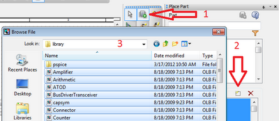
This is because you have no libraries loaded. Capture/PSpice is built for high-end engineers who will be importing all sorts of really specific and complex circuit parts. They want just fucking-exactly the parts they use. That's not your problem, you want the simple stuff.

Import the ones under 'pspice'. In practice they seem to be the only ones that will work in a simulation. Probably because they're the one ones with 'pspice' models.


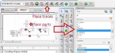
Now that you actually have parts to place, make a circuit. And when you're done making it, add traces to it. When the simulation for this circuit runs it will only show you data about the traces you add.


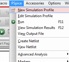
When the circuit is done, now make a simulation. The simulation will have parameters like start-time, end-time and a bunch of others. For now, only fiddle with the start and end time.


When you're done setting up the simulation, hit 'run'. This will launch PSpice, the computer will do a bunch of thinking, and then it will tell you what your circuit has been doing.

If you get errors here, maybe you had PSpice up already and you need to close it all first. Maybe you added parts that have parameters that you didn't fill out. Other than that, don't be afraid to google it. Orcad's PSpice is very opaque and the internet is filled with chats from people who are frustrated trying to do the same should-be-simple task you are.

Wednesday, January 25, 2012

Failure


You're going to fuck it up. We both know that you have no idea what you're doing. Success is about coming up with a strategy that can tolerate what a colossal failure you are.

For instance, 'relentlessness' is a solid strategy for engineering. You will put the part in backwards and fry the whole circuit. It will teach you to design more resilient circuits and add fail safes. You will weld the part on upside down. And the moment you do, drop everything and go out to get a grinder. If you waste even a minute thinking about what this means for the rest of the project, you will fail at this project. If you do this often, it's why you fail often. You can ask questions like 'why did I do that' in the shower or when you're staring at the ceiling after sex.

'Completing projects' is not a realistic strategy for engineering. For starters 'finishing' isn't a goal you can realistically take action on or achieve. You don't know what it's going to take to finish. You're never built this device before. You're learning as you go. You don't know what you're doing, stop expecting to have benefits like 'predictability' or 'quality'. You will not because you're a fucking novice at this. And if you're not a novice at this task, it's time to stop being a human factory, that's what machines are for.

Focusing on completion when you're doing work you haven't done a million times before will only demoralize you when you watch your self-imposed release date and intended design slip and slip from under your feet. It will demoralize you. Expecting success will make you feel like a failure when you have no idea what you're doing. Which is exactly the position you're in when you're learning. So don't expect success. Expect progress.

Stop trying to predict. Stop trying to 'finish'. You don't know how to do that. Just make progress. If you make continuous progress, finishing will coming on it's own.

Sunday, January 15, 2012

Man fork


My friends and I were talking about grill tools. There's a claim to be made that grill tools are too classy, too costly, too fragile, and too fucking small.

Having not thought about the problem at all, I don't see why I can't make one tool that handles all my camping-cooking-fire needs for less than $10 and an hour's work.


I've always found it's important to gather requirements by having outlandish fantasies of greatness.

I don't want to have to change tools between killing zombies and roasting their bodies in the heat of a post-apocalyptic office-tower conflagration. It'll need to save me time while I'm drawing "don't worry, I got this shit" in fire-lit letters on the abandoned highway with their smoldering bodies. And then I'll want to use the same tool for cooking bacon and pancakes in the morning for the gun-slinging nuclear scientist after we begin the re-population process in the back of a tank.

So I'm imagining kind of like a really big fork. With, eh, I guess a spatula on the other end. Strong enough that you could play baseball with it.

So what do we have lying around here to work this out with? Some 6"x20ish" 16 gauge steel plate, 4'x1"x1/8" angle steel, and a 2'x1/4" steel rod.


Of course we're going to need a lot of bad-ass industrial equipment to turn that pile of steel into awesome. Moments like this are why I live with a 90Amp MIG welder in my kitchen.

But first, let's start with the band-saw next to the couch. I'll only need a few cuts but they're going to be a bitch to do without this machine. If you're about to do this holding a chunk of steel over a cardboard box with a hack saw... then I know exactly how you feel because I did that shit for like 10 years. It sucks. If you're going to get one metal-working tool... well fuck, you should actually probably get the welder because no amount of elbow grease is going to melt that fucking steel. But if you get two tools... get some vice grips. Eventually get a band saw. These things are a fucking there-is-no-god-but-engineers-saved-my-ass-send.


It's a good thing the neighbors play a lot of video games because it makes me feel better about the 10 minutes of deafening metal-on-metal screech at 7:00 on a Sunday night.


So now we've got the parts we need. Time to haul the grinder out on the deck. If I'm going to build a cooking utensil capable of felling a horseman, it'll have to be razor sharp. Hell, I might even use the 'fine-grain' cutting wheel. For the pronged end, I'm thinking just two spikes with 30ish deg points. For the flipper/shovel, a light bevel will do fine and maybe even rounding out the edges. Don't want to rip those fluffy flap jacks while the lady is watching. It'll be important to show some finesse after the tough and tumble I showed her up against that nuclear weapon I've been carting around. (It was a perfect choice for an engagement present.)


Now it's time to get some weld on. The 16 gauge steel can't take much heat so I'll have to turn it down a little. Also, to hell with clamping things down. It's a man-fork, not a microscope. Just put the pieces nearby each other in the configuration needed and paint with the welder. Sure it'll be a few millimeters off but that hardly matters. Besides, this whole thing is supposed to take less than an hour.

Sent some sparks around, quenched it in the nearby snow, and now I've got a real ass-kicker. One cheap and easy to make tool that will kick the ass of any store-bought grill utensil.

Go forth and fabricate!