Friday, December 31, 2010

Slimming down


It turns out it's taking ~1.5ms to drain each capacitor as they fire. If the projectile is 2cm long and going 50m/s, it's length will pass in just 400ms. I've put in an order for smaller capacitors that I'll use in the place of the 1800uF ones I have now.

As a result, I've got some time to kill before I can put on more accelerating gates...

Since design I'm using now puts the firing circuits right next to each magnet, there's less need for overarching support circuitry and thus less room taken up in the rear of the rifle. This means I can cut off some of that extra metal to slim it down. Of course, I'll have to brace it and very carefully on piece off at a time.

It also means I'm going to spend some time cutting meta, which I hate because it takes forever. If you have to do this, I recommend getting the largest pair of bolt cutters you can find. Making the major cuts with the bolt cutters will keep the milling and hack-sawing part of the job to a minimum. As you can see from the pictures I've taken about 6cm off the bottom.

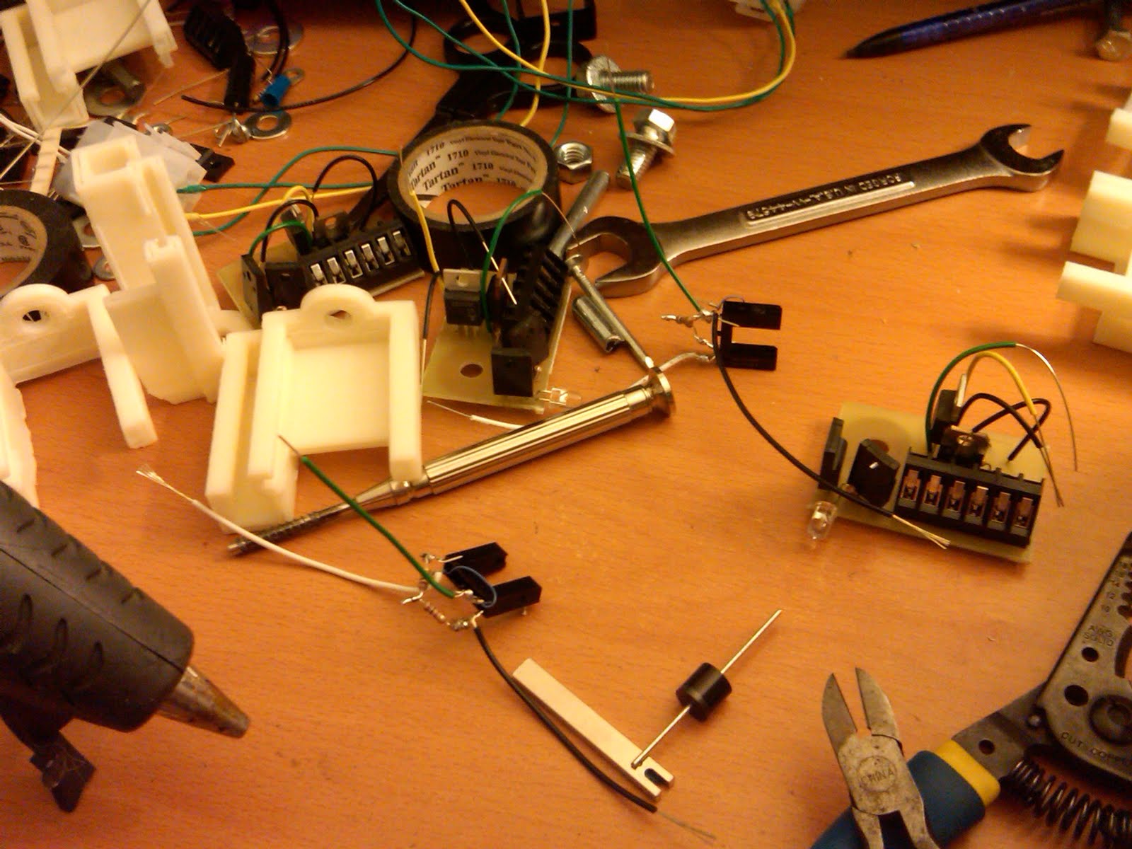
Since I'm just waiting on the capacitors, I've also take the opportunity to solder the parts on to all the remaining firing circuits. I only have 9 so I'll need to get another board's worth printed but 9 should get me most of the way.

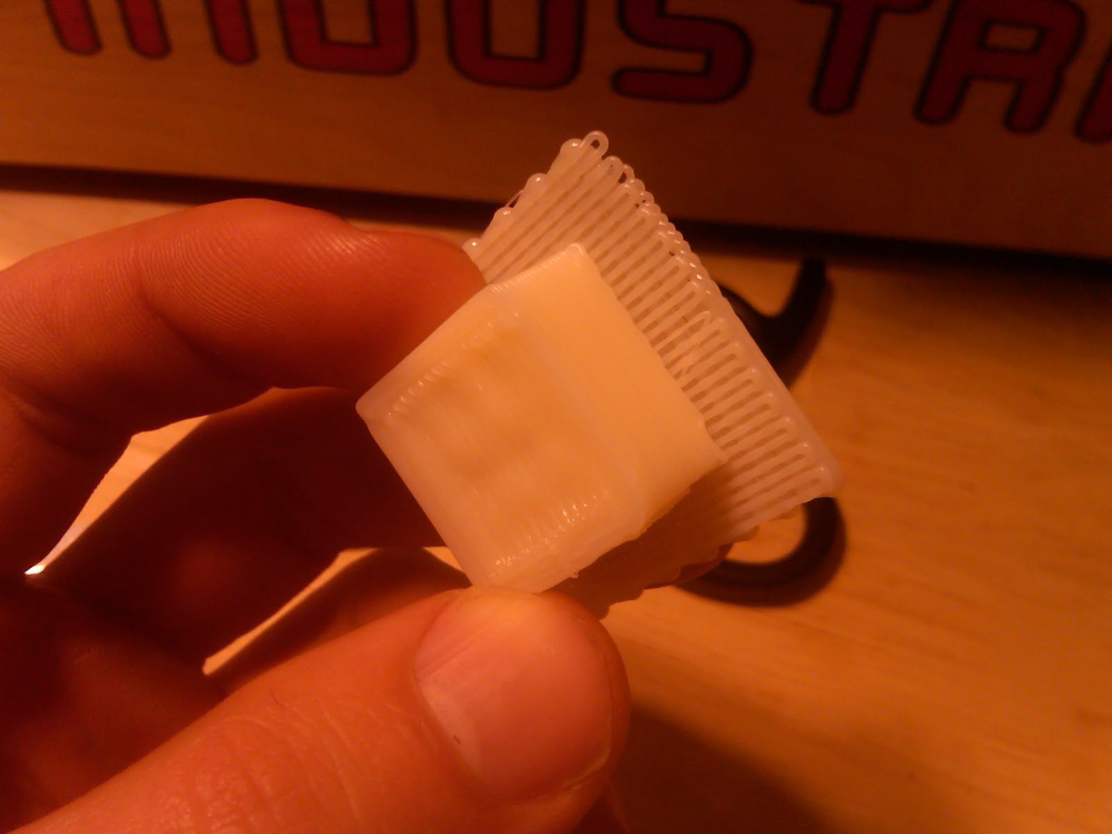
I've also had the 3d printer working overtime. In a couple places I need to remove the bracing on the brackets of have ones that are slimmer to accommodate the fact that I've unevenly cut the printed circuit boards. Well, that's the beauty of the printer: 1-off products coming up no problem. :)

Tuesday, December 28, 2010

Firing results: Top speed of 51m/s


Now that we've got the 3d printer, I'm able to mount the firing boards. It did turn out, however, that home depot only had 2 more of the brackets I use to mount the capacitors. I'll have to work something out there.

In the meantime, I was able to easily get 2 more magnets working (for a total of 4). They worked the very first time I fired them up and now I've got some test results with both a large projectile and a smaller one.

I think the larger projectile didn't fire efficiently at the beginning because it wasn't moving fast enough to see the returns from the subsequent gates firing. I think the smaller projectile fired less efficiently at higher voltages because it was already moving too fast and the later gates were able to add less and less to it's velocity.

The large projectile should have a higher top speed because it takes longer to move through the magnet and thus the magnet can be allowed to fire for longer. In either case, we will begin to see diminishing returns on those projectiles.

Assuming we don't want to change the barrel, this leaves essentially just one option: Reduce the size of the capacitors so they fire faster. However, this also means they have less energy to drive into the process. The only way to get that energy capacity back is to raise the voltage. Odds are the projectile is already well into magnetic saturation but might as well try it.

All that said, we still have to test the timing of the firing of later magnets to show that they really are lagging behind the projectile. That shouldn't be too hard.

Large projectile


Voltage (V)Time (S)Velocity (m/s)Proj E (J)Cap E (J)Efficiency
2000.0216516.631.601441.11%
3000.0092438.968.803242.72%
4000.0071250.5614.835762.57%


Small projectile


Voltage (V)Time (S)Velocity (m/s)Proj E (J)Cap E (J)Efficiency
2000.0086841.474.561443.17%
2500.0078445.925.592252.48%
3000.0072449.726.553242.02%
3500.0070850.856.854411.55%

Friday, December 24, 2010

Back to building products. No more fucking around building tools.


The 3D printer is actually doing it's job: I've got a bracket. It turns out the smallest wall the machine can realistically do in this shape is 3mm so that's the size I build the holder to.

I also have the new circuit boards which I've cut and soldered up one of. I waited to print brackets till I had them because I don't know the size for sure till I've got the boards and frankly it's not a big deal to make brackets anymore so I can just do it at the time I need them :).

I did remember, however, that each of the firing boards has a big-fuck 1000kOhm, 10W resistor that it needs. I've re-engineered the brackets to have a holder. I'd print them now but the sis is in the living room reading (the machine squeaks and smells a bit). She'd tolerate it, but this holiday season the gift I'm giving is not-being-a-fucker.

Code of the machine:
circuitLength = 50;

circuitWidth = 36;

circuitDepth = 3;

circuitLip = 3;

bedToBoltCenter = 22; //Distance between the bottom of the barrel holder and the mounting bolt for each barrel section

bedWidth = 40; //How wide the bar that holds the barrel is.

boltDiameter = 8;

wallThickness = 3;

resistorWidth = 11;

resistorTopSlat=6;


//a = 10;

//X is along the length of the circuit

//y is along the barrel length

//z is up

module circuitHolder()

{

difference()

{

union() //Added parts

{

translate([circuitLength/2+ wallThickness/2,0,0])

cube(size=[wallThickness+circuitLength, wallThickness*2 + circuitWidth, wallThickness*2 + circuitDepth], center=true);

rotate([0,-90,0]) //bolt

cylinder(h=30,r=(boltDiameter/2+2*wallThickness),center=true);

translate([bedWidth/2,0,-bedToBoltCenter/2-circuitDepth/2])

cube(size=[bedWidth,circuitWidth,bedToBoltCenter-circuitDepth/2],center=true);

translate([circuitLength/2+ wallThickness/2,-resistorWidth/2-circuitWidth/2,-wallThickness-circuitDepth/2-resistorWidth/2]) //Resistor holder

cube(size=[wallThickness+circuitLength,wallThickness*2 + resistorWidth, wallThickness*2 + resistorWidth], center=true);

}

union() //Removed parts

{

translate([circuitLength/2 + wallThickness + 1,0,0])

cube(size=[circuitLength+1, circuitWidth, circuitDepth], center = true);

translate([circuitLength/2 + wallThickness + 1,0,0])

cube(size=[circuitLength+1, circuitWidth - 2*circuitLip, circuitDepth+wallThickness*2+100],center= true);

rotate([0,-90,0]) //Bolt

cylinder(h=30,r=boltDiameter/2,center=true);

translate([-50,0,0])

cube(size=[100,100,100],center=true);

translate([0,0,-bedToBoltCenter-2 ]) //Edge to accomidate bend in the holding bar

rotate([0,45,0])

cube(size=[15,300,15],center=true);

translate([circuitLength/2+ wallThickness/2,-resistorWidth/2-circuitWidth/2,-wallThickness-circuitDepth/2-resistorWidth/2]) //Resistor holder cut-out

cube(size=[wallThickness+circuitLength+2,resistorWidth, resistorWidth], center=true);

translate([circuitLength/2+ wallThickness/2,-resistorWidth/2-circuitWidth/2,0]) //Resistor top slat

cube(size=[wallThickness+circuitLength+2,resistorTopSlat, resistorWidth], center=true);

}

}

}

//rotate([0,-90,0])

circuitHolder();

//translate([0,0,-10])

//cube(size=[30,30,20], center=true);

Monday, December 20, 2010

3d pinter: First object


(see bottom for video)

The printer required some more hassle. Including switching the x-axis plug to get it running in the right direction, really tightening down the plastic feeder switch, and some really special calibration of the z-axis. Again, I'll stress that I'd be happy if it was 2x the size but much more serviceable. Then again, it's pretty cool that my 3d printer is smaller than my milling machine.

Print time was pretty fast. And the extrusion was quite small. As the directions note, it does smoke a bit the first few times and has a bit of an odor. I think that's just what happens when you take a chunk of epoxy and electronics up to 220 deg C.

I printed a 2cm x 2cm x 1cm brick. It weighs in at 3.9g. That means the material is about 1000kg per cubic meter. Since the plastic is about $33/kg that object, if you could print it, would come out to about $33,000 per cubic meter or about $0.032 per cubic centimeter. That's a pretty good price for being able to make anything you want.

As for durability, this thing is a brick for sure. I can bend the platform but the brick itself does not bend or give in any sort of way. Once I show it around I'll cut it in half and post the results.

3d printer: That was a bitch and a half, but it works


Construction takes about 2 full days. Main things to watch out for:
* Tension your belts at the time you install them, not at the end. Waiting till the end means disassembly.
* Have a magnet handy to hold things in tight spots.
* Be extra careful when building the X-Y axis piece, it's the hardest to get at when you're done.
* This is hardware, not software. It really is 10x more time to fix it after the fact than to do it right the first time.

That said, ever part works. The software can talk to the motors, the heating elements, etc. The end switches work. The firmware update worked. It all looks good and I've done basic tests of everything.

Next step:
* Run the heating elements to 220 deg C and do some practice extrusion.

Assuming it passes that... we're ready to try our first test print.

Saturday, December 18, 2010

3d pinter: More trashing the aparment


Got the X and Y axis done. Now working on the extruder head.

Well, according to the instructions I've got the Y axis done, but it sill haven't mounted the motor for it so I'm not sure if I'd count that one complete.

As for the extruder head, it's actually quite a simple little thing. There's a brick of steel with resistors bolted to it. The plastic wire feeds in through an insulated channel till it hits the extruder head at the very end and melts. (Or at least that's how it appears to work, given I've never seen it do so.)

Thursday, December 16, 2010

3s printer: Finished the build platform


Insta-converted the living room into an additional work room... In that now all the rooms are work rooms. Also, got the build platform done.

Everything is fitting together perfectly and I've not found any parts missing. It is worth having a magnet though for holding small parts in place.

Wednesday, December 15, 2010

A 3d pinter! kinda...


Looks like I was in the very first shipment of Makerbot Thing-o-matics. It's actually just a pile of parts.

One upon a time, we had water cannons for our ship that could only be filled at any reasonable speed by dipping them in water. This meant bending over the side, about 2 feet down into the water. This would always be the job of girls wearing bikinis for obvious reasons.

There's a certain nerd with cleavage I'm thinking of for a similar job to help with the makerbot... But all yall are welcome!

Saturday, December 11, 2010

Some totally unintelligable BS about a circuit I've not explained well


The new circuits work excellently. It looks like I do have a couple design issues with them. First, I'm missing a slot of a diode that should prevent a fully charged capacitor from leaking back through the indicator light to an uncharged capacitor. Secondly, there's no hole in there for the wire that connects to the gate of the main SCR. Finally, there's no place to put the large resistor connecting the pre-firing SCR and the main SCR.

How could you not be interested in that? It's like I took something that's already hard to explain and then didn't explain it at all but instead just gave an arbitrary status update!

Wednesday, December 8, 2010

Printed circuits: The charger


Seeing as how the first circuits I've had printed are going so well, I did a version of the charger circuit. It looks like there are a few connections I can't do by just printing on one side so I've also added a few connections that need to be made still with wire wrapping.

Monday, December 6, 2010

PCB Singles: They didn't scam me


Finally got around to checking the mail today: PCB board is here! Looks like what I ordered and the parts even fit in it. (Haven't soldered them yet so I don't know if I did it right, but they seem to have done their job)

One not of complaint is that it comes glued to a chunk of cardboard and the adhesive won't let go of the circuit board. gotta remember to never use that area. Kind of a easily fixed fail for such an otherwise perfect experience, but it's workable.

Wednesday, December 1, 2010

Getting down and dirty with shunt resistors


I'm firing the accelerator at ~400V. The red line is whatever. The blue line is the voltage across a 0.02 ohm resistor in line with the firing circuit. It looks like it's got about 20V across it, though my scope rails out at 10V. This works out to about 1000A or around half a megawatt at peak, given that the main coil is running at 400V.

Most importantly though we can see the coil is running at high power for about 1ms. That is a very long time. If the projectile is 2cm long that means we'll experience significant deceleration at just 20m/s. Perhaps we've not seen that yet because the second coil (which would be the one decelerating since the round is already moving >20m/s when it gets there) is firing well before the round and only using a piece of it's accelerating power.

Given that we don't want to make a new coil, the alternative is decreasing the capacitance. Halfing the capacitance will half the firing time. This, of course, goes hand-in-hand with increasing the voltage to pick up the additional power.