Thursday, November 11, 2010

Quick initial results


I fired at 250V (of 450V max), using 2 of the accelerator gates (later to be 13, but they'll be of different dimensions so hard to compare that now). The projectile was clocked at 20m/s. More specifically, it took 7.6ms to pass a distance of 15cm. (I'll post later about how I do ballistic measurement.)

I was using some relatively beefy SCRs in a Super-247 package but I toasts them heartily anywhere beyond 200Vs. Instead I switched to a bolt-style SCR that's been doing fine. Oddly they have exactly the same characteristics on their datasheets. Clearly one of them is lying. Too bad too, cuz the one I toasted was only $6 and the other one is $26. It'll need more than one of two of these things before the project is done.

Bolt style: http://ixdev.ixys.com/DataSheet/L106.pdf
247 style: http://www.vishay.com/docs/93712/93712.pdf

Wednesday, November 10, 2010

I makes me feel like less of a man

I just did a small test to show that it works not just firing one of the magnets but actually using two of them. There's still a lot of work to do but this shows that the prototype wiring is all correct (or at least close enough).

This shot was taken at 100V or about 1/8th power. It also only used two of the magnets. In the final version there will be 12 of them. That comes out to about 2% power. In reality I probably won't get the power out of later ones that I might want so call it about 5% power.

Also, finally got a working credit card again so the buying continues:
* T-slot nuts for the milling machine
* Helmet cam so I don't have to use the cell-phone
* An ass ton of electronics from digikey (or I will later tonight after I debug one last thing)

Monday, November 8, 2010

High power analog is a little bitch and always has been

I've set it up to be able to fire on two of the magnets as a test.

It does indeed charge and fire. That said, the electromagnetic disturbance caused by just the charging system seems to be able to set off the SCRs that fire the magnets whenever it charges above 130V (the electromagnetic disturbance from the charger gets more agressive as the voltage increases. Indeed, you can hear it once it passes about 100V). The reason I get this pre-firing is that the magnets are set off by an infared beam sensor. When the round breaks the beam, the sensor gives a signal to the firing circuit. It seems that the disturbance is enough to cause bumps in the signal and thus fire the magnet before it's supposed to. At one point, when it fired while charging, the charger seems to have been able to toast one of the firing circuits.

My solution right now is to put a computer (microcontroller) between all the sensors and the firing circuits. The computer will be able to see when the signal is bouncing and discount it. I could also use a capacitor-resistor filter for this but that would provide less flexibility in the long run.

The computer will have it's own 5V power supply and need not share one with the charger. This should also help reduce jitters.

Sunday, November 7, 2010

The duct-tape approach

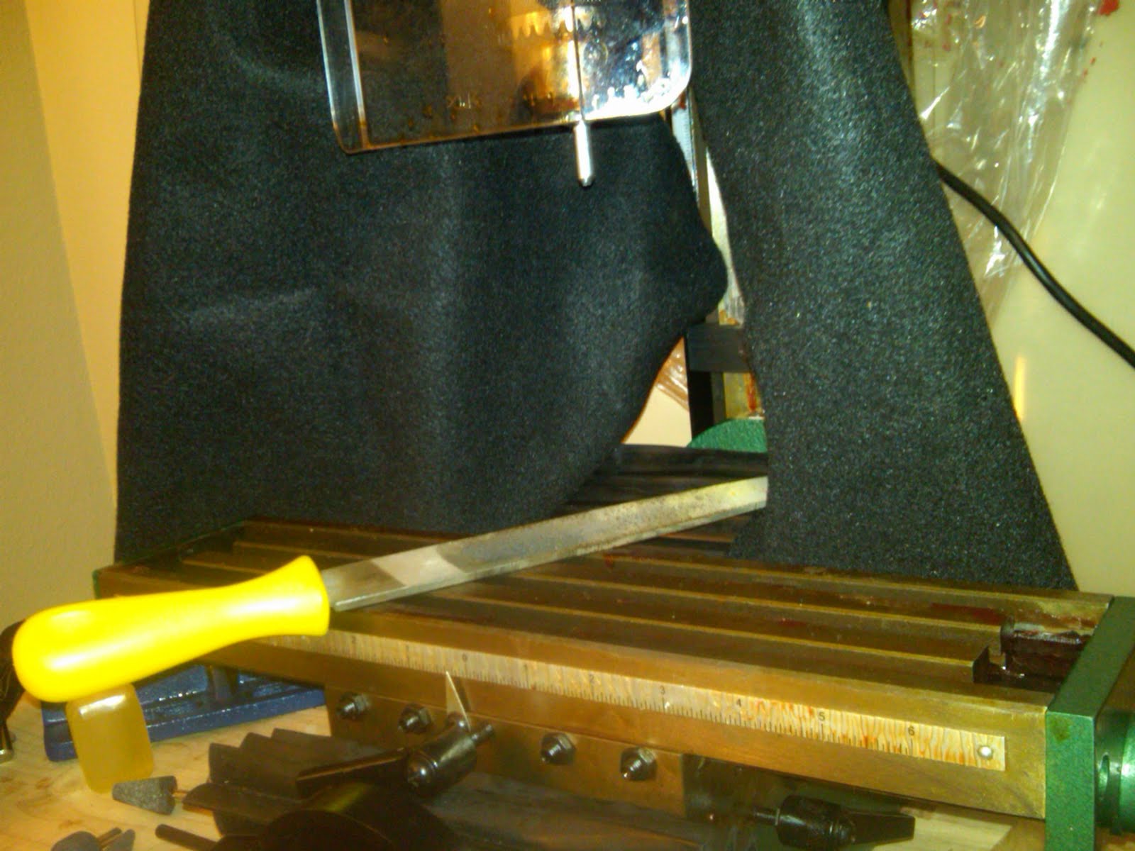
Instead of buying a lathe... I got a cheap file. I cut the bolt and mounted it in the chuck. It spins. I press. Takes longer than you'd think, but it sure works.

I have no idea what I'm doing.

It turns out I have no idea how to operate a milling machine.

My goal here is making ammunition for the rifle out of bolts. Specifically, I want to put a point on the chunk of bolt that I'm going to be shooting. To accomplish this, I intend to mount the bolt vertically and then used a metal filing bit that already has an angle to it. All I'll need to do is rotate the milling head around the bolt to make it pointed.

In the end, it sure beats doing it by hand with a file but it's clearly going to take a while. Additionally, it's pretty clear I have no idea how to use the mounting set. In this situation I've set it up to work well forward and backwards but it can slide to the left and right.

I need to mount the milling machine to the table next time I do this because I intend to tilt the head to the side and just use a normal milling bit to cut away at it from and angle.

This job totally demands a lathe. Like the one job I can imagine I'll ever have to do that demands a lathe instead of a milling machine...

Saturday, November 6, 2010

Getting messy


Machine kept falling over, so I added a brace. Not fancy, the but the theme of recent construction is 'get it done'.

Been working mostly on getting the overall wiring diagrams done. There will be a succession of 12 electromagnets, each will need identical wiring but I don't want to have any point that has a breakout of 6 different wires times 12 magnets. That would be a disaster. Instead I'm going for a daisy chaining design where each plugs into the next one. Hopefully that won't mean too many failure points and power lost through connections but we'll see.


Even with that simplification, there's a need for a central junction to which many different systems can connect. Last time I did this, I just made a specialized connector. It worked but that was a mistake from a recycle-and-modify-the-parts-later standpoint. I still don't like the junction connector but next time I'll remember to make room for it somewhere on the device itself instead of just having it hang out up in the front of the rifle as it'll likely be doing.

Monday, November 1, 2010

Forget all that: Too complex


For V1 I won't be using the aluminium main bar as stated earlier. I believed at one time I could just print off and throw brackets at it but it looks like some of them will require drilling. That could be as many as 8 holes per electromagnet (of which there are 12) and even that at odd angles. Also, the cost of the ABS plastic for the 3d-printer won't be zero.

Instead, I'm going to use a steel bar wherever possible.

The bars to hold racks of components are a bit long but I'll cut them later. It looks like I can squeeze all the major stuff (big ass battery included) into just the top-half of the space I have.