Tuesday, January 25, 2011

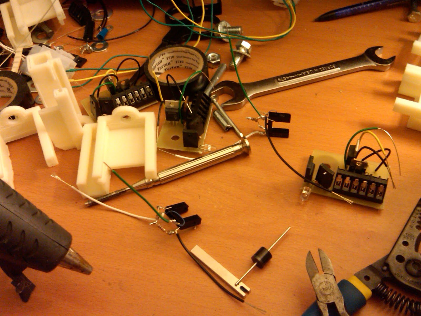
New SCR holding brackets and firing circuit board


Finally got the new brackets printing. They're far simpler and I'll need another kind for the new circuit board (now that I've got the printed version) as well as the big ass resistors that board uses.

As you can see I've also got new black plastic on a spindle so the makerbot can just feed and build nearly forever.

That machine was a great investment. The objects are cheap (essentially free) and surprisingly durable. I actually put one on the strong table I've also got my milling machine and started hammering it; it doesn't even show damage. I'll do an official tensile strength test at some point.


Code for the part:
frontNeck = 4.5;
rearNeck = 13;
scrWidth = 18.2;//16.8;
scrHeight = 15.5;//14;
scrFitDepth = 20;
boltDiameter = 8;
boltNutWidth = 12.5;//11;
boltHexWidth = 7.2; //tan(pi/6)*boltNutWidth
boltNutHeight = 5;
boltCarrierRadius = 6;
boltToScrDistance = 6;
//fitDepth = 10;
totalLength = 33;//43;
wallThickness = 3;
bedToBoltCenter = 18;

module circuitHolder()
{
difference()
{
union()
{
translate([totalLength/2,0,-bedToBoltCenter/2-scrWidth/4-wallThickness/2+scrWidth/2+wallThickness])
cube([totalLength,scrHeight+2*wallThickness,bedToBoltCenter+scrWidth/2+wallThickness],center=true);
// rotate([0,-90,0]) //bolt
// translate([0,0,-wallThickness/2-boltNutHeight/2])
// cylinder(h=wallThickness+boltNutHeight,r=(boltDiameter/2+boltCarrierRadius),center=true);
//translate([totalLength/2,scrHeight/2+wallThickness/2,-bedToBoltCenter/2+boltCarrierRadius])
// cube([totalLength,wallThickness,bedToBoltCenter+boltCarrierRadius],center=true);
//translate([totalLength/2,-scrHeight/2-wallThickness/2,-bedToBoltCenter/2+boltCarrierRadius])
// cube([totalLength,wallThickness,bedToBoltCenter+boltCarrierRadius],center=true);
}
union()
{

translate([scrFitDepth/2+rearNeck/2+boltNutHeight+wallThickness+boltToScrDistance,scrHeight,0]) //horizontal slots

cube([scrFitDepth+rearNeck/2,scrHeight,rearNeck],center=true);
translate([scrFitDepth/2+rearNeck/2+frontNeck/2+boltNutHeight+wallThickness+boltToScrDistance-2,-scrHeight,0])
cube([scrFitDepth+frontNeck/2,scrHeight,frontNeck],center=true);
translate([0,0,-bedToBoltCenter-2-4]) //Edge to accomidate bend in the holding bar
rotate([0,45,0])
cube(size=[15,300,15],center=true);
translate([totalLength/2+1+boltNutHeight+wallThickness,0,0]) //main SCR holder
cube([totalLength+2,scrHeight,scrWidth],center=true);
rotate([0,-90,0]) //Bolt
cylinder(h=100,r=boltDiameter/2,center=true);
translate([boltNutHeight/2+1/2+wallThickness,0,0])
{
union()
{
rotate([0,0,0])
cube([boltNutHeight+1,boltNutWidth,boltHexWidth],center=true);
rotate([60,0,0])
cube([boltNutHeight+1,boltNutWidth,boltHexWidth],center=true);
rotate([120,0,0])
cube([boltNutHeight+1,boltNutWidth,boltHexWidth],center=true);
}
}//translate
}//removal union
} //difference
}


rotate([0,-90,0])
circuitHolder();
//translate([0,0,-10])
//cube(size=[30,30,20], center=true);

Monday, January 17, 2011

I've finally got it under control


It looks like I've finally got the timing and EMF noise issues under control. This mostly involved moving the firing logic into a computer instead of a single-purpose circuit and putting in shielding.

In the long run adding the computer will mean less wiring as the computer can handle a number of the firing circuits. In the short run, it means the circuits I've been making are a waste. I can use them for the first few stages but as more precision is needed later they can't do the job.

You can see from the graph that as I change the delay (x-axis) I can get a fall in the time between speed measuring gates (y-axis). The fact that this relationship exists implies that I'm actually adding power to the munition again and ass I add and tune more magnets in the future that munition will actually go faster.

On the plus side, when looking at this graph it's clear that the region-of-good-performance is quite wide. The numbers correspond to at least 300us of delay from one end of that region to the other (and it may even be as wide at 600us). At the speed of 50m/s our 4cm round is passing a location in 800us. If we essentially don't care about the position of that round for 300us of that 800us, we're really only using 500us for acceleration. At 4cm in length, this means we should be able to hit 4cm/500us = 80m/s before we see degradation in the performance of each magnet. At the optimistic max of 600us, we could see 200m/s before we begin to see that loss of efficiency.

Next step: Getting this prototype magnet controller to scale up to 13 of them.

Sunday, January 9, 2011

Check it out: I'm not making progress!!


I've made an obvious mistake. I assumed that I'd just need to downsize the caps and the pulse of power would be shorter. I failed to consider the obvious problem that inductance controls the rise time. I'm simply not rising the amperage fast enough. Even smaller caps won't speed things up.

Of course, I discovered this after installing smaller and smaller caps. It'll do about 55m/s but no faster.

You can see the waveforms in the attached pictures. The red one is where the cap is at 600uF. The blue is when I put 2 600s in series to cut their capacitance. Clearly we go from 1ms to 500us as expected.

There are a couple options at this point.
* Lead the munition - Fire well in advance of it's arrival. When it does get there, it'll change the inductance of the coil and hopefully absorb most of the energy in it, cutting the flow of current from the cap.
* Force the SCRs down - Lead the munition but then fire a dump scr to drain the energy when the munition arrives.
* Rebuild the barrel with lower inductance on the later stages - With lower inductance, we'll reach peak amperage faster and I'll still be able to use small caps and fire at the time.

Of course, doing #1 and #2 don't require rebuilding a big portion of the machine so I'll do those first.

Sunday, January 2, 2011

More accelerating magnets


I've added a few more accelerating magnets. As noted before, I can't really enable them because my capacitors are too large. I've also found a new issue.

The main symptom was that the device failed to charge correctly. Specifically it went up to about 60V and would go no further. I'd seen this issue before where the optical sensors were receiving interference from the electromagnetically noisy charging circuit: They'd fire when there was no bullet and the charger would fight to charge them as they discharged. For some reason, that fight was always resolved between about 60V and 90V of charge. My old solution was to add an override that kept all the optical gates as max voltage when charging. This signal was daisy chained just like all the others from charging circuit to charging circuit. Clearly there was something wrong with this signal. Adding my oscilloscope to view it while charging actually made the device charge correctly! Damn quantum circuitry pisses me off every time.

That said, the scope really adds one of two things to a circuit: a big resistor to ground (which can sometimes fix errors where your voltage is floating) and a capacitor between the measured voltage and ground. I assumed that perhaps the daisy chaining of this signal was causing it to not reach the firing gates in time to shut them off before the charger went ballistic making electromagnetic noise (it is a bit of a race, since both at turned on by the same switch trigger). I added a cap between the signal and ground and sure enough the issue went away. For about 30 minutes. Damn it.

Around that time I stared to notice the display wander when the capacitor voltage was low and even didn't turn on at one point. Something was up but I was too dense to discover the real issue until fired the device wearing a shirt. Thing is, the stock of the rifle is where the battery (24V) and, more importantly the rectifier that brings it down to 5V live. It's also steel and in this case it was warm. Reaching inside, I found the heat sink of the 1.5A 5V regulator was piping hot. It was almost certainty producing low voltage.

I stepped out to buy a pair of new 5V regulators that should get me to at least 7.5A:
http://search.digikey.com/scripts/DkSearch/dksus.dll?vendor=0&keywords=576-2254-ND
http://search.digikey.com/scripts/DkSearch/dksus.dll?vendor=0&keywords=LT1083CP-5%23PBF-ND

When I came back, the power supply was cooler and the device was charging correctly again.

Thing is, I didn't think I'd need more power. When all is said and done, the total consumption of 5V power should only be equivalent to a 5ohm resistor (or about 1A of power). That is 13 accelerator gates where each gate has a 200ohm resistor powering the optical sensor and a 100ohm resistor being pulled down on the mosfet that fires the little SCR (which in turn fires the big SCR). I only have like 8 of them installed so I should have even more buffer room. Something is sucking power.

Friday, December 31, 2010

Slimming down


It turns out it's taking ~1.5ms to drain each capacitor as they fire. If the projectile is 2cm long and going 50m/s, it's length will pass in just 400ms. I've put in an order for smaller capacitors that I'll use in the place of the 1800uF ones I have now.

As a result, I've got some time to kill before I can put on more accelerating gates...

Since design I'm using now puts the firing circuits right next to each magnet, there's less need for overarching support circuitry and thus less room taken up in the rear of the rifle. This means I can cut off some of that extra metal to slim it down. Of course, I'll have to brace it and very carefully on piece off at a time.

It also means I'm going to spend some time cutting meta, which I hate because it takes forever. If you have to do this, I recommend getting the largest pair of bolt cutters you can find. Making the major cuts with the bolt cutters will keep the milling and hack-sawing part of the job to a minimum. As you can see from the pictures I've taken about 6cm off the bottom.

Since I'm just waiting on the capacitors, I've also take the opportunity to solder the parts on to all the remaining firing circuits. I only have 9 so I'll need to get another board's worth printed but 9 should get me most of the way.

I've also had the 3d printer working overtime. In a couple places I need to remove the bracing on the brackets of have ones that are slimmer to accommodate the fact that I've unevenly cut the printed circuit boards. Well, that's the beauty of the printer: 1-off products coming up no problem. :)

Tuesday, December 28, 2010

Firing results: Top speed of 51m/s


Now that we've got the 3d printer, I'm able to mount the firing boards. It did turn out, however, that home depot only had 2 more of the brackets I use to mount the capacitors. I'll have to work something out there.

In the meantime, I was able to easily get 2 more magnets working (for a total of 4). They worked the very first time I fired them up and now I've got some test results with both a large projectile and a smaller one.

I think the larger projectile didn't fire efficiently at the beginning because it wasn't moving fast enough to see the returns from the subsequent gates firing. I think the smaller projectile fired less efficiently at higher voltages because it was already moving too fast and the later gates were able to add less and less to it's velocity.

The large projectile should have a higher top speed because it takes longer to move through the magnet and thus the magnet can be allowed to fire for longer. In either case, we will begin to see diminishing returns on those projectiles.

Assuming we don't want to change the barrel, this leaves essentially just one option: Reduce the size of the capacitors so they fire faster. However, this also means they have less energy to drive into the process. The only way to get that energy capacity back is to raise the voltage. Odds are the projectile is already well into magnetic saturation but might as well try it.

All that said, we still have to test the timing of the firing of later magnets to show that they really are lagging behind the projectile. That shouldn't be too hard.

Large projectile


Voltage (V)Time (S)Velocity (m/s)Proj E (J)Cap E (J)Efficiency
2000.0216516.631.601441.11%
3000.0092438.968.803242.72%
4000.0071250.5614.835762.57%


Small projectile


Voltage (V)Time (S)Velocity (m/s)Proj E (J)Cap E (J)Efficiency
2000.0086841.474.561443.17%
2500.0078445.925.592252.48%
3000.0072449.726.553242.02%
3500.0070850.856.854411.55%

Friday, December 24, 2010

Back to building products. No more fucking around building tools.


The 3D printer is actually doing it's job: I've got a bracket. It turns out the smallest wall the machine can realistically do in this shape is 3mm so that's the size I build the holder to.

I also have the new circuit boards which I've cut and soldered up one of. I waited to print brackets till I had them because I don't know the size for sure till I've got the boards and frankly it's not a big deal to make brackets anymore so I can just do it at the time I need them :).

I did remember, however, that each of the firing boards has a big-fuck 1000kOhm, 10W resistor that it needs. I've re-engineered the brackets to have a holder. I'd print them now but the sis is in the living room reading (the machine squeaks and smells a bit). She'd tolerate it, but this holiday season the gift I'm giving is not-being-a-fucker.

Code of the machine:
circuitLength = 50;

circuitWidth = 36;

circuitDepth = 3;

circuitLip = 3;

bedToBoltCenter = 22; //Distance between the bottom of the barrel holder and the mounting bolt for each barrel section

bedWidth = 40; //How wide the bar that holds the barrel is.

boltDiameter = 8;

wallThickness = 3;

resistorWidth = 11;

resistorTopSlat=6;


//a = 10;

//X is along the length of the circuit

//y is along the barrel length

//z is up

module circuitHolder()

{

difference()

{

union() //Added parts

{

translate([circuitLength/2+ wallThickness/2,0,0])

cube(size=[wallThickness+circuitLength, wallThickness*2 + circuitWidth, wallThickness*2 + circuitDepth], center=true);

rotate([0,-90,0]) //bolt

cylinder(h=30,r=(boltDiameter/2+2*wallThickness),center=true);

translate([bedWidth/2,0,-bedToBoltCenter/2-circuitDepth/2])

cube(size=[bedWidth,circuitWidth,bedToBoltCenter-circuitDepth/2],center=true);

translate([circuitLength/2+ wallThickness/2,-resistorWidth/2-circuitWidth/2,-wallThickness-circuitDepth/2-resistorWidth/2]) //Resistor holder

cube(size=[wallThickness+circuitLength,wallThickness*2 + resistorWidth, wallThickness*2 + resistorWidth], center=true);

}

union() //Removed parts

{

translate([circuitLength/2 + wallThickness + 1,0,0])

cube(size=[circuitLength+1, circuitWidth, circuitDepth], center = true);

translate([circuitLength/2 + wallThickness + 1,0,0])

cube(size=[circuitLength+1, circuitWidth - 2*circuitLip, circuitDepth+wallThickness*2+100],center= true);

rotate([0,-90,0]) //Bolt

cylinder(h=30,r=boltDiameter/2,center=true);

translate([-50,0,0])

cube(size=[100,100,100],center=true);

translate([0,0,-bedToBoltCenter-2 ]) //Edge to accomidate bend in the holding bar

rotate([0,45,0])

cube(size=[15,300,15],center=true);

translate([circuitLength/2+ wallThickness/2,-resistorWidth/2-circuitWidth/2,-wallThickness-circuitDepth/2-resistorWidth/2]) //Resistor holder cut-out

cube(size=[wallThickness+circuitLength+2,resistorWidth, resistorWidth], center=true);

translate([circuitLength/2+ wallThickness/2,-resistorWidth/2-circuitWidth/2,0]) //Resistor top slat

cube(size=[wallThickness+circuitLength+2,resistorTopSlat, resistorWidth], center=true);

}

}

}

//rotate([0,-90,0])

circuitHolder();

//translate([0,0,-10])

//cube(size=[30,30,20], center=true);