Let's say I wanted to build a mech warrior. A big walking robot.
I want to drive it on the road. A quick check of the laws says a max of 8.5' wide and 14' tall before you're a 'oversize load'. 14' tall is reasonable. Let's say 10 for legs, 4 for cockpit (you'll be sitting, maybe stretch those legs out).
What about power? They won't sell civilians nukes and I probably can't afford one anyways. So it'll have to be gas or diesel. But what about the actuators? This is too big for electric servos. Can't do pneumatics because they don't offer much in the way of position control: the gas will exert a certain pressure at a certain volume so generally pneumatics have to be railed out in one direction or another else their position will be unstable. Might also consider just a bunch of mechanics that move the legs at just the right times. But then it'll never be able to do dynamic things like crouch or lean forward. So it'll have to by hydraulics. They can hold position well. They're super strong. They're not terribly expensive.
If you're not familiar with hydraulics, don't worry, I'm not either. From what I read, there's no like 'reservoir of pressure' since hydraulic fluid is inelastic. So you have to pump up the actuators using an engine in real time. Here is such an engine: http://www.fostermfgcorp.com/page/gas/20_24_hp.html
Gas powered. 25 HP. 15 gal/min pumping speed @ 2000psi. That pumping speed is going to be a set rate probably even when the psi it needs to push is lower because it's probably just an engine turning some little pump at a set RPM. The pump moves a certain volume at that RPM and is rated to a max pressure of 2000. Notice how they come at different max pressures and volume rates. If they could dynamically run move volume at a lower pressure they wouldn't be priced like that.
How much can that engine power? Let's do some calculations about the mech. The engine is 450 lbs right off the bat. Two passengers is 350 lbs assuming a dude and a chick. Cockpit structure and fuel is say 200 lbs. If we say each leg is two 7' spans of I-beam at a 1/2" thick, 2" edge-wide, 3" center-wide then we have 588 cubic inches of steel in each leg. At 0.226 lbs/cu-in that's 133 lbs/leg. The feet will probably have to be at least that beefy since the force angles on them will be terrible and they'll have to be big for stability. Let's round leg weight up to 500 for actuators and feet. Total weight: 2000lbs.
How much force is on one of those legs? Let's assume the two spans that make up a leg are inverted, like chickens have. The knee is pointing backward and the acute angle of the knee faces forward. Near the hip, the leg is connected on a joint. Then there's a hydraulic actuator that connects a point farther down the leg to the hip. When that actuator expands, it pushes the thigh section to be more vertical and less horizontal. But where is the actuator exactly positioned?
Let's say the knee is at a 90 degree angle when standing. So the leg is at 45 degrees to horizontal. And let's put the actuator straight up and down while standing.
If we look up cylinders on McMasterCarr we see that a pretty common stoke length is 1' on a cylinder that's 1.5' long compressed. http://www.mcmaster.com/#62205kac/=gv8y5j
In the standing position we'll need the cylinder to be at least somewhat uncompressed because it will need to compress more if we ever want to take a step backward. So let's put it at 1.8' extension while standing. If it uncompresses out to 2.5' (it's max extension) and we put it, say 1.5' from the hip joint, the actuator will be able to move the thigh from an angle of 45 deg while standing to 68 deg (the math takes up some room so you'll just have to do it yourself or trust me). That's some, not a lot of angle. It'd be nice if the leg could at least get to vertical (90 degrees). But whatever, this is a first order approximation.
Again, how much weight is on this actuator? While standing the thigh is at a 45 deg angle, it's 7' long and the connection point is 1.5' away from the joint. So we have 2000lbs but it's being leveraged at 7*cos(45)/1.5 = 3.3x. The actuator feels 6,600 lbs.
Sure, we could move the actuator farther from the hip joint to reduce that multiplier but then our max extension angle would be even smaller.
What kind of actuator do we need for 6,600 lbs? Actuator strength is all about bore size and pressure. Power = pi * r^2 * pressure. Our engine runs up to 2000 psi. That returns a bore size of almost exactly 1". Let's use the 1.5" bore for safety. It will give us a 2.25x safety margin before the engine explodes or the mech collapses under it's own weight.
How quickly can our engine move that actuator? At a 1' stroke with a 1.5" bore we're going to consume 85 cubic inches of hydraulic fluid. Remember our engine can do 15 gal/min or 15*231 = 3,465 cubic inches per minute. 58 cubic inches per second. It can fully extend that actuator in 1.47 seconds. But if we assume there are 3 actuators per leg (hip-thigh, thigh-calf, calf-foot) and we're extending each of them only half way we're able to put one leg forward in 2.2 seconds. If an actual step is leg-forward, weight forward, leg-return we'll be taking a step every 7 seconds or so.
That's a slow step. It better be a big one.
How can we speed that up? Well, a nuke with a bigger hydraulic pump wouldn't hurt.
Wednesday, March 28, 2012
Wednesday, March 21, 2012
Chris was right


I should be using an H bridge. For some reason I had it stuck in my mind that supplying the gate voltage to the high-end transistors was going to be a bitch. It won't be a bitch. I just need to man up.
Sunday, March 18, 2012
Circuits: They make your abstraction barriers into their bitches
The goal: Making a DC motor controller that can reverse directions. This will be used on the grabber arm for the table mentioned in previous posts.
The initial concept: Make a DC rectifier that goes one way, turn it on when you want to go that way. Let's try it:

So let's talk through this circuit. Far on the left we see the power source, I found it in the 'SOURCE' library in Orcad PSpice. It has a 60Hz wave with 60V amplitude. I chose 60V because going higher seemed to short out the other parts in the simulation. In real life I'll buy better parts.
Below the power source is a square wave generator. I'm going to use it to turn the circuit on and off. It's set to trigger a 20V high for 0.05s and repeat that ever 0.2 seconds. When it's at 20V I expect the motor to be getting power. When it's at 0V I expect the motor to be off.
Moving to the right, we have that odd part marked 2N5444. That's a triac. It's two silicon controlled rectifiers (SCRs) hooked up together. (If you aren't familiar with what these are, go look up diodes, then look up SCRs, then look up tiacs. Don't be afraid, you're here to learn electrical engineering, and it is complex. There will be a lot to learn so start now.) This device will essentially conduct current when it gets power.
Moving farther to the right, we have a bridge rectifier. It takes an AC voltage and converts it into DC. (If you've not seen one before, take a second to think about how this works)
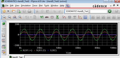
Finally, on the far right we have a resistor which is acting as the motor. I've put two voltage traces on it so we can see how much power it's getting.

Looking at the simulation result we can see that in fact the motor is getting DC power because the green line is always above the red line. So the polarity of the power on the motor is always the same. Sure it bounces around all over with the AC input, but we can fix that later with capacitors.

Now let's try extending the circuit. I've essentially mirrored it but this time made two changes. First I hooked up the motor backward relative to the DC power I'm applying. If this works, the motor will run backwards when this second circuit is triggered. I also set it's trigger to be different from the first one. I gave it an offset so now it should run forward for a bit, turn off for a bit, run backward for a but, turn off for a bit, and repeat.

In practice, this shit doesn't work at all. The two bridge rectifiers interfere and the voltage across the motor is always zero. It totally breaks the abstraction barrier I was trying to make.
I discovered this in the process of thinking about this circuit, but it took a lot of thinking to realize that and the computer would have told me it wouldn't work. That said, the computer wouldn't have told me why. And I did need to know why.
With circuits, this shit is going to do weird stuff all the time. In the simulation, like real life, it's not going to work as you planned. I'm a reasonably smart person and it is proven to me every day that I have no idea what I'm doing. I'm going to be you don't know what you're doing either. So let's muddle through this.
My next step: thinking up a motor controller that'll actually work. Or, fuck if it comes to that, actually looking up designs for them like I should have done already.
The initial concept: Make a DC rectifier that goes one way, turn it on when you want to go that way. Let's try it:

So let's talk through this circuit. Far on the left we see the power source, I found it in the 'SOURCE' library in Orcad PSpice. It has a 60Hz wave with 60V amplitude. I chose 60V because going higher seemed to short out the other parts in the simulation. In real life I'll buy better parts.
Below the power source is a square wave generator. I'm going to use it to turn the circuit on and off. It's set to trigger a 20V high for 0.05s and repeat that ever 0.2 seconds. When it's at 20V I expect the motor to be getting power. When it's at 0V I expect the motor to be off.
Moving to the right, we have that odd part marked 2N5444. That's a triac. It's two silicon controlled rectifiers (SCRs) hooked up together. (If you aren't familiar with what these are, go look up diodes, then look up SCRs, then look up tiacs. Don't be afraid, you're here to learn electrical engineering, and it is complex. There will be a lot to learn so start now.) This device will essentially conduct current when it gets power.
Moving farther to the right, we have a bridge rectifier. It takes an AC voltage and converts it into DC. (If you've not seen one before, take a second to think about how this works)
Finally, on the far right we have a resistor which is acting as the motor. I've put two voltage traces on it so we can see how much power it's getting.

Looking at the simulation result we can see that in fact the motor is getting DC power because the green line is always above the red line. So the polarity of the power on the motor is always the same. Sure it bounces around all over with the AC input, but we can fix that later with capacitors.

Now let's try extending the circuit. I've essentially mirrored it but this time made two changes. First I hooked up the motor backward relative to the DC power I'm applying. If this works, the motor will run backwards when this second circuit is triggered. I also set it's trigger to be different from the first one. I gave it an offset so now it should run forward for a bit, turn off for a bit, run backward for a but, turn off for a bit, and repeat.

In practice, this shit doesn't work at all. The two bridge rectifiers interfere and the voltage across the motor is always zero. It totally breaks the abstraction barrier I was trying to make.
I discovered this in the process of thinking about this circuit, but it took a lot of thinking to realize that and the computer would have told me it wouldn't work. That said, the computer wouldn't have told me why. And I did need to know why.
With circuits, this shit is going to do weird stuff all the time. In the simulation, like real life, it's not going to work as you planned. I'm a reasonably smart person and it is proven to me every day that I have no idea what I'm doing. I'm going to be you don't know what you're doing either. So let's muddle through this.
My next step: thinking up a motor controller that'll actually work. Or, fuck if it comes to that, actually looking up designs for them like I should have done already.
Saturday, March 17, 2012
Circuit simulation: How to do it
If you intend to make a cool machines in this day and age, sooner or later you'll have to learn/do electrical engineering.
Circuit simulation will save you money and time. It's cheaper than buying parts you don't need or turning the ones you need into smoke. It's faster than soldering and unsoldering things.
It also has a higher barrier to entry than playing with physical objects. This is because the software for circuit simulation is designed to be as intuitive as electricity itself. So let me walk you though it.

The most common, most powerful, and frankly best software is Orcad's PSpice. You can get the 'lite' version free and it does almost everything.
Orcad sells a million other products and you don't want them. You only want 'capture' and PSpice.

Once you download and install it, open Capture and only Capture. If you have PSpice open first when you open Capture it won't work right, seriously. Capture is the circuit designing software. PSpice is the analysis system that Capture will automatically launch when the time comes.
Once you're in Capture, make a new project. If it asks you about inheritance, just set it to no inheritance, that will only confuse things. You want the 'Mixed Analog and Digital' style project. Eventually you should end up on a blank screen that has icons on the side for placing wires and whatnot but no parts. If you click on the parts icon you'll see nothing.
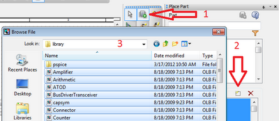
This is because you have no libraries loaded. Capture/PSpice is built for high-end engineers who will be importing all sorts of really specific and complex circuit parts. They want just fucking-exactly the parts they use. That's not your problem, you want the simple stuff.
Import the ones under 'pspice'. In practice they seem to be the only ones that will work in a simulation. Probably because they're the one ones with 'pspice' models.
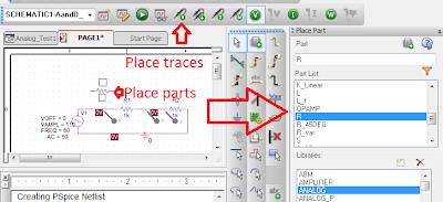
Now that you actually have parts to place, make a circuit. And when you're done making it, add traces to it. When the simulation for this circuit runs it will only show you data about the traces you add.
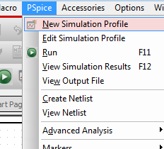
When the circuit is done, now make a simulation. The simulation will have parameters like start-time, end-time and a bunch of others. For now, only fiddle with the start and end time.
When you're done setting up the simulation, hit 'run'. This will launch PSpice, the computer will do a bunch of thinking, and then it will tell you what your circuit has been doing.
If you get errors here, maybe you had PSpice up already and you need to close it all first. Maybe you added parts that have parameters that you didn't fill out. Other than that, don't be afraid to google it. Orcad's PSpice is very opaque and the internet is filled with chats from people who are frustrated trying to do the same should-be-simple task you are.
Circuit simulation will save you money and time. It's cheaper than buying parts you don't need or turning the ones you need into smoke. It's faster than soldering and unsoldering things.
It also has a higher barrier to entry than playing with physical objects. This is because the software for circuit simulation is designed to be as intuitive as electricity itself. So let me walk you though it.

The most common, most powerful, and frankly best software is Orcad's PSpice. You can get the 'lite' version free and it does almost everything.
Orcad sells a million other products and you don't want them. You only want 'capture' and PSpice.

Once you download and install it, open Capture and only Capture. If you have PSpice open first when you open Capture it won't work right, seriously. Capture is the circuit designing software. PSpice is the analysis system that Capture will automatically launch when the time comes.
Once you're in Capture, make a new project. If it asks you about inheritance, just set it to no inheritance, that will only confuse things. You want the 'Mixed Analog and Digital' style project. Eventually you should end up on a blank screen that has icons on the side for placing wires and whatnot but no parts. If you click on the parts icon you'll see nothing.

This is because you have no libraries loaded. Capture/PSpice is built for high-end engineers who will be importing all sorts of really specific and complex circuit parts. They want just fucking-exactly the parts they use. That's not your problem, you want the simple stuff.
Import the ones under 'pspice'. In practice they seem to be the only ones that will work in a simulation. Probably because they're the one ones with 'pspice' models.

Now that you actually have parts to place, make a circuit. And when you're done making it, add traces to it. When the simulation for this circuit runs it will only show you data about the traces you add.

When the circuit is done, now make a simulation. The simulation will have parameters like start-time, end-time and a bunch of others. For now, only fiddle with the start and end time.

When you're done setting up the simulation, hit 'run'. This will launch PSpice, the computer will do a bunch of thinking, and then it will tell you what your circuit has been doing.
If you get errors here, maybe you had PSpice up already and you need to close it all first. Maybe you added parts that have parameters that you didn't fill out. Other than that, don't be afraid to google it. Orcad's PSpice is very opaque and the internet is filled with chats from people who are frustrated trying to do the same should-be-simple task you are.
Subscribe to:
Posts (Atom)